
Views: 298 Author: Dingnuo Electric Publish Time: 2026-08-28 Origin: Site


Content Menu
● What Is the Difference Between SVG and SVC?
>> Why SVG Performs Better During Voltage Dips
● SVG vs. SVC: Performance Differences That Matter
>> Response Speed and Load Tracking
>> Low-Voltage Reactive Support
>> Harmonics and Resonance Risk
● When Is an SVC Still a Good Choice?
● A Practical Selection Process for Industrial Plants
>> 1. Measure the Load Profile
>> 2. Conduct a Harmonic Survey
>> 3. Define the Actual Objective
>> 5. Verify Installation Conditions
● Expert View: Compensation Must Be System-Specific
● FAQ
>> What is the main difference between SVG and SVC?
>> Is SVG the same as STATCOM?
>> Which is faster: SVG or SVC?
>> Can SVG eliminate harmonics?
>> Can an SVG correct both inductive and capacitive power factor?
>> How do I choose the correct SVG capacity?
In industrial power systems, choosing between an SVG (Static Var Generator) and an SVC (Static Var Compensator) directly affects power factor, voltage stability, harmonic risk, equipment reliability, and operating cost. For plants with rapidly changing loads, frequent motor starts, welding equipment, arc furnaces, variable-frequency drives, or sensitive automation systems, the wrong compensation technology can lead to under-compensation, over-compensation, voltage fluctuation, and avoidable downtime.
At DINGNUO ELECTRIC CO., Ltd., we work with industrial power-quality applications where reactive power compensation must be designed around actual load behavior—not simply around a nameplate kVar value. This guide explains the practical difference between SVG and SVC, their operating principles, strengths, limitations, and selection criteria for industrial power systems.

Both SVG and SVC are reactive power compensation solutions. Their shared goal is to improve power factor, reduce reactive-power demand from the grid, support voltage quality, and improve the efficiency of electrical distribution systems.
However, they use fundamentally different technologies.
- SVC is an impedance-based compensation system. It commonly combines thyristor-controlled reactors, thyristor-switched capacitors, fixed capacitor banks, and harmonic filters.
- SVG is a power-electronic, current-source-type compensator. It uses an IGBT-based voltage-source converter and coupling reactor to inject or absorb the required reactive current dynamically.
In simple terms, an SVC changes the effective capacitive or inductive impedance connected to the network. An SVG actively creates the reactive current the system needs.
This distinction becomes especially important when the voltage is unstable, the load changes quickly, or harmonic-producing equipment is present.
| Comparison Item | SVG / STATCOM | SVC |
|---|---|---|
| Core technology | IGBT-based voltage-source converter | Thyristor-controlled reactor and capacitor branches |
| Compensation method | Continuously injects or absorbs reactive current | Changes system susceptance through reactors and capacitors |
| Reactive power regulation | Stepless and bidirectional | Stepwise or quasi-continuous, depending on configuration |
| Typical response | Often within a few milliseconds | Commonly tens of milliseconds |
| Low-voltage performance | Maintains stronger reactive-current support | Reactive output decreases substantially as voltage falls |
| Harmonic behavior | Can be designed for low distortion; may support harmonic compensation in specific configurations | Usually requires filters and careful resonance analysis |
| Footprint | Often more compact for comparable dynamic performance | Can require large reactors, capacitors, and filter branches |
| Initial investment | Generally higher | Often lower for stable, conventional loads |
| Suitable load profile | Rapidly changing and sensitive loads | Relatively slow, predictable load variation |
The central selection question is not "Which product is better?" It is: Which technology matches the electrical behavior, harmonic profile, voltage conditions, and operating priorities of the facility?
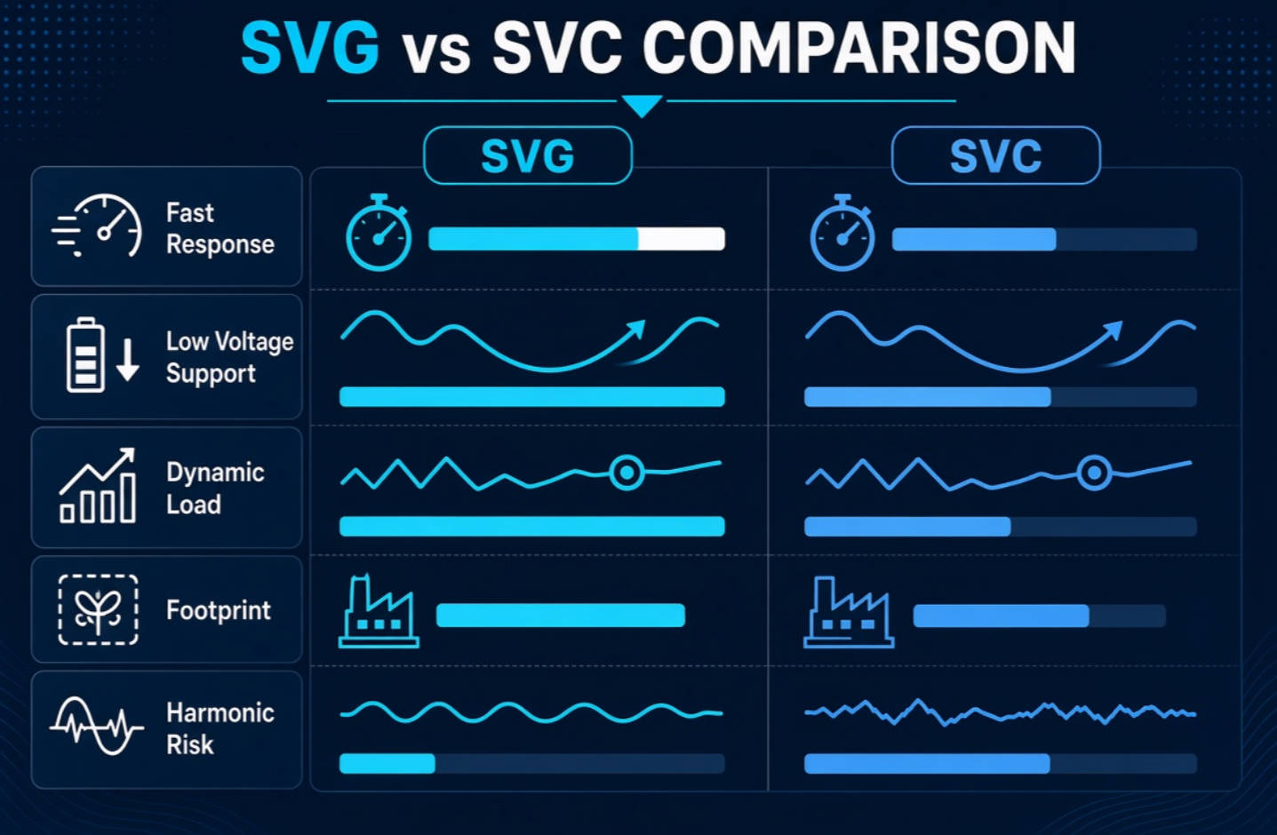
An SVC is a static reactive power compensation system based on thyristor switching and controllable reactor branches. Typical SVC configurations include:
- Thyristor-Controlled Reactor (TCR)
- Thyristor-Switched Capacitor (TSC)
- Fixed Capacitor–Thyristor-Controlled Reactor (FC–TCR)
- Harmonic filter capacitor banks
- Mechanical switched capacitor banks in lower-speed systems
When a system requires capacitive reactive power, capacitor banks are switched in or reactor current is reduced. When the system requires inductive reactive power absorption, the reactor branch is controlled to absorb vars.
This design has made SVC a proven solution for many utility, substation, and industrial applications. It can be economically attractive where load changes are relatively slow and predictable.
- Mature technology with a long record in transmission and industrial systems
- Suitable for large reactive-power ratings
- Can be cost-effective in stable-load applications
- Can combine compensation and harmonic-filter functions
- Useful where space is available and response requirements are moderate
The main limitation is that SVC reactive-power output depends strongly on bus voltage. Its available output follows an approximate voltage-squared relationship:
QSVC∝V2
When bus voltage drops, the available reactive support from an SVC also falls significantly. This can be a serious concern during voltage dips, motor-starting events, process disturbances, or fault recovery.
SVC systems also require careful engineering around capacitor banks, reactors, detuning, and harmonic filters. If the system impedance and filter design are not properly coordinated, resonance may amplify harmonic currents or voltages rather than reduce them.
An SVG, also commonly described as a low- or medium-voltage STATCOM, uses an IGBT-based converter to generate a controllable AC voltage behind a coupling reactor. By controlling the converter output relative to the grid voltage, the SVG can inject capacitive reactive current or absorb inductive reactive current.
Unlike traditional capacitor-bank compensation, an SVG does not depend on discrete switching steps to follow a changing load. It delivers continuous, stepless compensation.
When inductive loads such as motors, transformers, welding machines, crushers, rolling mills, and VFD-driven equipment draw lagging reactive power, the SVG supplies capacitive reactive current. When the system becomes overcompensated or capacitive, the SVG can absorb reactive current.
SVG reactive-current capability is much less affected by voltage variation than SVC behavior. In practical terms, SVG offers stronger support when voltage conditions are weak or unstable.
Industry analysis from CIGRE explains that SVC reactive output declines approximately with \(V^2\), while STATCOM output decreases more nearly in proportion to \(V\). This difference makes a converter-based SVG particularly valuable in dynamic voltage-support applications.
For industrial users, this may mean better voltage control during:
- Large motor starting
- Arc furnace operation
- Rolling-mill load changes
- Spot welding cycles
- Crusher and conveyor load swings
- Rapidly changing VFD loads
- Weak-grid or long-cable distribution conditions
- Fast response for rapidly changing reactive-power demand
- Continuous compensation with no conventional capacitor-bank switching steps
- Bidirectional operation, supplying or absorbing reactive power
- Stronger performance under voltage fluctuation
- High power-factor control accuracy
- Compact installation compared with large capacitor/reactor/filter assemblies
- Lower risk of capacitor switching transients
- Better suitability for systems with dynamic loads
SVG is not automatically the right answer for every site. Its initial purchase cost is usually higher than that of a conventional capacitor-bank or basic SVC solution. It also requires correct sizing, ventilation design, protection coordination, communications integration, and harmonic measurement.
A poorly specified SVG can still fail to solve the real problem. For example, an SVG selected only for power-factor correction may not provide sufficient harmonic-current mitigation if the plant's primary issue is excessive harmonic distortion.
The response time of a reactive power compensation system determines how well it follows changing loads.
SVC response commonly occurs in the millisecond-to-tens-of-milliseconds range, depending on topology and control design. SVG systems can respond more rapidly because IGBTs are controlled electronically and continuously. One comparative technical source cites response figures below 10 ms for SVG/STATCOM and about 20–30 ms for SVC systems. [cigre]
This difference matters when load demand changes faster than conventional capacitor or reactor stages can follow.
For example, a welding workshop may experience sharp, repetitive changes in reactive demand. An SVC may provide useful bulk compensation, but an SVG is often better suited to track the fast load swings and avoid repeated over- or under-compensation.
At reduced voltage, an SVC loses reactive-power capability more quickly because its output is linked to the square of system voltage. By contrast, an SVG behaves more like a controlled current source, maintaining more effective support through voltage variation.
This is particularly relevant for facilities with:
- Weak incoming utility supply
- Long feeder lines
- Large transformer impedance
- High starting currents
- Frequent voltage dips
- Large fluctuating loads
Neither SVG nor SVC should be selected without a power-quality assessment.
SVC systems often use capacitors and reactors, and they may include harmonic-filter branches. These branches must be properly engineered to avoid resonance with the upstream network. Harmonic conditions can change when production equipment, transformers, cable lengths, capacitor stages, or utility network conditions change.
SVG systems use converter technology and can be designed with low harmonic output. Certain active power-filter or hybrid SVG solutions can also compensate selected harmonic currents. However, standard SVG functionality should not be confused with a full active harmonic filter.
IEEE 519-2022 establishes harmonic-control objectives for electrical systems with nonlinear loads and applies steady-state voltage and current distortion limits at the point of common coupling. A professional site study should therefore measure actual harmonic current, voltage distortion, source impedance, transformer loading, and likely resonance frequencies before selecting a solution.
SVG is generally the stronger choice when the site needs precision, speed, and reliable performance under changing operating conditions.
Choose an SVG when your facility has:
- Rapidly changing reactive loads
- Welding machines or robotic welding cells
- Electric arc furnaces or induction furnaces
- Rolling mills, mining equipment, crushers, and conveyors
- High concentrations of VFDs, soft starters, UPS systems, or rectifier loads
- Frequent voltage fluctuations or flicker complaints
- High power-factor targets, such as 0.99 or near unity
- Capacitive overcompensation during light-load production
- Tight installation space
- A need for dynamic, automated compensation
DINGNUO ELECTRIC solutions can be engineered for power-quality environments found in metallurgy, petrochemical processing, automotive production, paper manufacturing, textile plants, building-material production, and municipal infrastructure projects.
In these sectors, the issue is often not simply "low power factor." The real challenge may involve a combination of fluctuating loads, harmonics, voltage deviation, transformer losses, and production-process sensitivity.
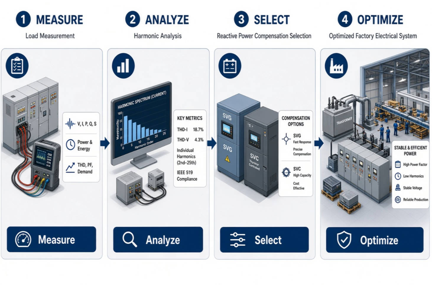
SVC remains a valid option in the right application. It may be suitable where the reactive-power requirement is large but changes relatively slowly, and where the electrical system can accommodate the physical space and harmonic-filter design.
Choose an SVC when:
- Load variation is gradual and predictable
- The main requirement is bulk reactive-power compensation
- The installation has adequate space for reactors, capacitors, and filters
- Initial capital cost is the primary decision factor
- The harmonic environment has been assessed and can be managed through engineered filters
- The facility can accept a less dynamic compensation response
For stable loads, a well-designed SVC may offer an economical and dependable solution. The key is to avoid treating it as a universal solution for every industrial electrical problem.
The best SVG or SVC decision begins with field data, not a generic product quotation.
Record load behavior across full production cycles, including startup, peak production, idle periods, and shift changes.
Measure:
- Active power in kW
- Reactive power in kvar
- Apparent power in kVA
- Power factor
- Voltage variation
- Current variation
- Transformer loading
Identify the main harmonic orders, total harmonic distortion, nonlinear load percentage, and possible resonance conditions.
Focus on:
- Voltage THD
- Current THD
- 5th, 7th, 11th, and 13th harmonic components
- Existing capacitor-bank operating conditions
- Transformer and cable impedance
- Point of common coupling requirements
Do not use a single device to solve every issue unless its design supports every required function.
Clarify whether the priority is:
- Power-factor correction
- Voltage stabilization
- Flicker reduction
- Harmonic mitigation
- Resonance control
- Capacity release at the transformer
- Avoidance of utility penalties
- Improved reliability for sensitive equipment
A compensation rating should account for maximum reactive demand, future expansion, load diversity, and the required response speed.
For example, a plant with a 1,000 kvar average demand but rapid swings between 200 kvar and 1,500 kvar may require a different solution from a plant with a steady 1,000 kvar demand. The dynamic range is as important as the average value.
Review the voltage level, transformer capacity, feeder arrangement, ambient temperature, ventilation, ingress-protection requirement, available floor space, and communication protocol.
This ensures the selected system is not only electrically correct but also practical to install, commission, and maintain.
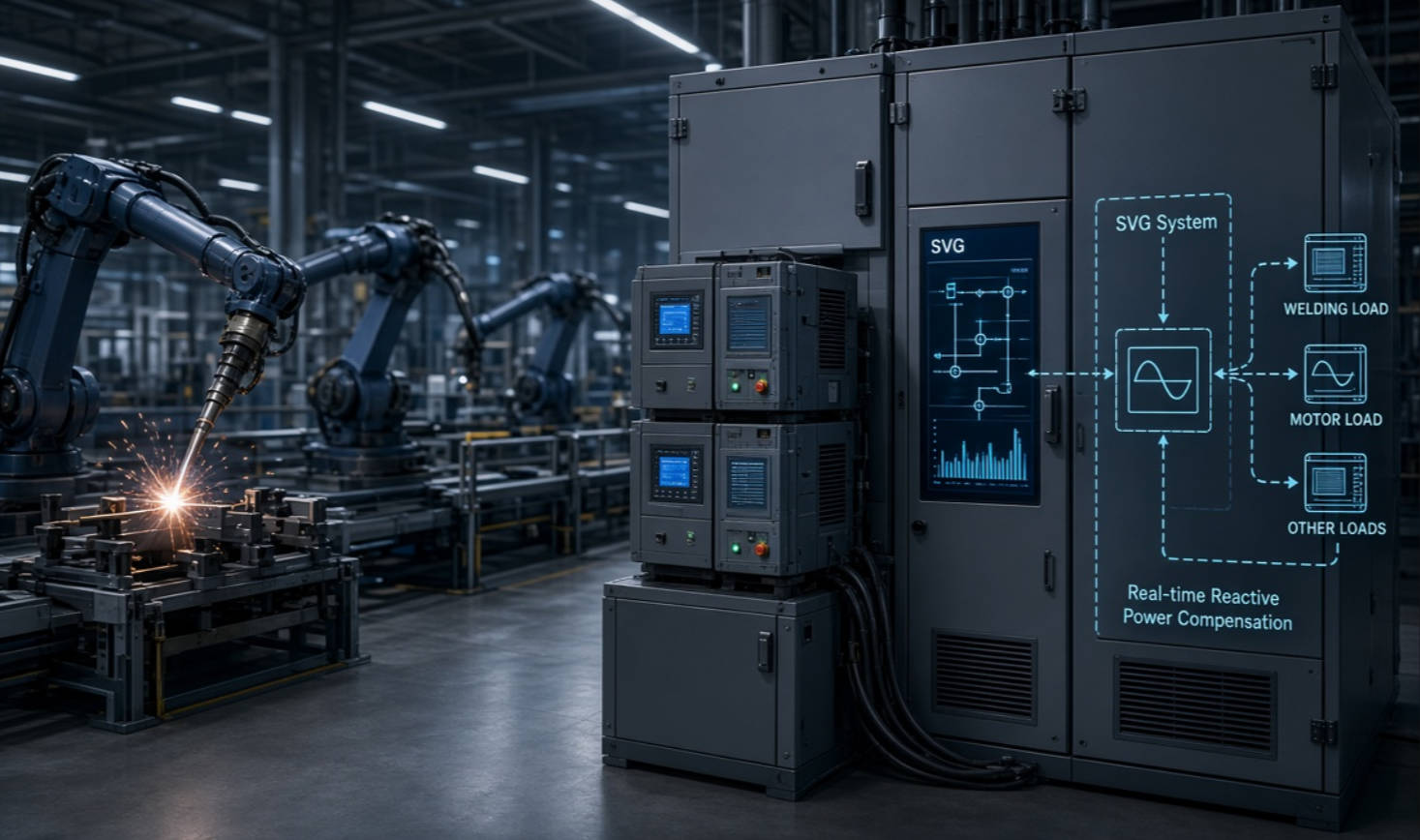
From an engineering perspective, the most common mistake is selecting a reactive compensation device only by kvar capacity.
A 600 kvar SVG and a 600 kvar SVC may have very different outcomes in the same facility because their response behavior, harmonic interaction, low-voltage capability, and control methods are different.
For a textile mill with mostly stable motors, an SVC may be commercially reasonable. For an automotive welding line with robotic cells, variable-speed drives, and rapid load fluctuation, an SVG may deliver better power-factor stability and voltage performance. For a metallurgical plant with both fluctuating load and severe harmonic content, the correct answer may be a coordinated SVG plus active harmonic filter or a hybrid compensation design.
The right solution should be based on measured electrical data, production behavior, local utility requirements, and the facility's reliability goals.
DINGNUO ELECTRIC CO., Ltd. provides capacitors, reactors, reactive power compensation equipment, and harmonic-control solutions for demanding industrial and municipal electrical systems.
Our technical approach starts with the operating conditions of your facility. We help evaluate reactive demand, load fluctuation, harmonics, voltage stability, installation constraints, and expansion plans—then recommend a practical solution built around your application.
Contact DINGNUO ELECTRIC today to discuss your power-quality challenge and request a technical assessment for SVG, SVC, capacitor-bank, reactor, harmonic-filter, or integrated compensation solutions.
SVG uses IGBT-based converter technology to continuously inject or absorb reactive current. SVC uses thyristor-controlled reactors and capacitor banks to regulate reactive power by changing system impedance.
In many industrial and commercial applications, SVG is used to describe a static synchronous compensator, or STATCOM. Terminology can vary by manufacturer, voltage class, market, and application, so buyers should verify the product topology and performance specifications.
SVG generally responds faster because it uses electronically controlled IGBT converters and stepless current control. SVC response depends on its thyristor and capacitor/reactor configuration and is commonly less suitable for extremely fast load variation.
A standard SVG is primarily a reactive-power compensation device. Some systems incorporate active harmonic filtering or hybrid functions, but buyers should confirm the specific harmonic-compensation capability, harmonic spectrum, and performance guarantee before purchasing.
SVC often has a lower initial investment for stable-load applications. However, total lifecycle value depends on installation space, filter requirements, maintenance, voltage-support needs, energy losses, production reliability, and utility power-factor charges.
Yes. An SVG can supply capacitive reactive current to compensate inductive loads and absorb reactive current when the system becomes capacitive. This bidirectional operation helps prevent overcompensation during light-load conditions.
Start with an electrical survey. Measure maximum and minimum reactive-power demand, voltage condition, harmonic distortion, load fluctuation speed, transformer capacity, and expected future expansion. A qualified supplier should use this data to propose the required rating and control strategy.
1. IEEE Standards Association. "IEEE 519-2022: Standard for Harmonic Control in Electric Power Systems." Available at: [IEEE 519-2022]. This standard defines harmonic-control objectives and steady-state voltage and current distortion limits at the point of common coupling. [standards.ieee]
2. IEEE Standards Association. "P519—IEEE Standard for Harmonic Control in Electric Power Systems." Available at: [IEEE P519]. [standards.ieee]
3. CIGRE U.S. National Committee. "STATCOM Application to Address Grid Stability and Reliability." Available at: [CIGRE STATCOM technical paper]. The paper discusses the different voltage-dependent reactive-power characteristics of SVC and STATCOM systems. [cigre-usnc]
4. CIGRE Russia. "Characteristics and Functions of MCSR, SVC and STATCOM." Available at: [SVC and STATCOM comparison]. [cigre]
5. KETE Transformer. "SVG vs. SVC: Functions, Working Principles, and Key Differences." Available at: [SVG vs. SVC guide]. [ketetransformer]


