
Views: 274 Author: Dingnuo Electric Publish Time: 2026-08-26 Origin: Site


Content Menu
● What Is an SVG in a Utility Substation?
● High Voltage SVG vs Low Voltage SVG: Core Difference
● High Voltage SVG for Transmission-Level Voltage Support
>> Where High Voltage SVG Performs Best
>> High Voltage SVG Limitations
● Low Voltage SVG for Local Power Quality Control
>> Where Low Voltage SVG Performs Best
>> Low Voltage SVG Limitations
● How Voltage Level Changes the Engineering Decision
>> 1. Define the Voltage-Control Objective
>> 2. Assess Dynamic Reactive-Power Demand
>> 3. Evaluate Grid Strength and Short-Circuit Ratio
>> 4. Complete a Harmonic Study Before Final Design
● High Voltage SVG vs Low Voltage SVG: Selection Matrix
● Practical Specification Checklist for Utility Buyers
● Expert Perspective: Do Not Treat SVG as a Standalone Box
● Choose the Right SVG Solution
● FAQ
>> 1. What is the main difference between high voltage SVG and low voltage SVG?
>> 2. Can a low voltage SVG replace a high voltage SVG?
>> 3. Which SVG is better for renewable-energy substations?
>> 4. Does an SVG remove harmonics?
>> 5. How should SVG capacity be sized?
>> 6. Can high voltage SVG absorb reactive power during low-load periods?
>> 7. Is SVG suitable for steel, cement, paper, and textile plants?
For utility substations, choosing between a high voltage SVG and a low voltage SVG is not simply a question of voltage class. It determines where reactive power is injected, how rapidly the grid can recover from disturbances, what harmonic risks must be controlled, and how much equipment must be installed around the converter.
At DINGNUO ELECTRIC CO., Ltd., we approach SVG selection from the operating problem backward: identify the voltage instability, reactive-power deficit or surplus, harmonic profile, short-circuit capacity, load dynamics, and substation topology first. Then select the connection voltage and system architecture that deliver the required performance with the lowest practical lifecycle risk.
Editor's note: In many international utility specifications, SVG is commonly described as a STATCOM (Static Synchronous Compensator). Both terms generally refer to a voltage-source-converter-based dynamic reactive-power compensation solution.
A Static Var Generator (SVG) is a power-electronics-based device that injects or absorbs reactive current to regulate voltage, improve power factor, increase transfer capability, and support grid stability.
Unlike switched capacitor banks, an SVG provides continuously controllable reactive power. Unlike conventional SVC systems, an SVG can maintain strong reactive-current support when voltage drops. This makes it especially suitable for substations affected by renewable-energy fluctuations, large motor starts, arc furnaces, weak-grid connections, rapidly changing industrial loads, and fault-related voltage recovery requirements.
An SVG typically includes:
- A voltage-source converter, often using IGBT or modular multilevel converter technology
- DC-link energy storage components
- AC reactors or coupling transformers
- Control and protection systems
- Harmonic filtering or harmonic-performance design measures
- Cooling, auxiliary power, communication, and monitoring systems
The basic operational principle is straightforward. The converter generates a controllable AC voltage. By adjusting that voltage relative to the grid voltage, the SVG either injects capacitive reactive current or absorbs inductive reactive current.
Key advantage: reactive current response is fast and continuously adjustable.
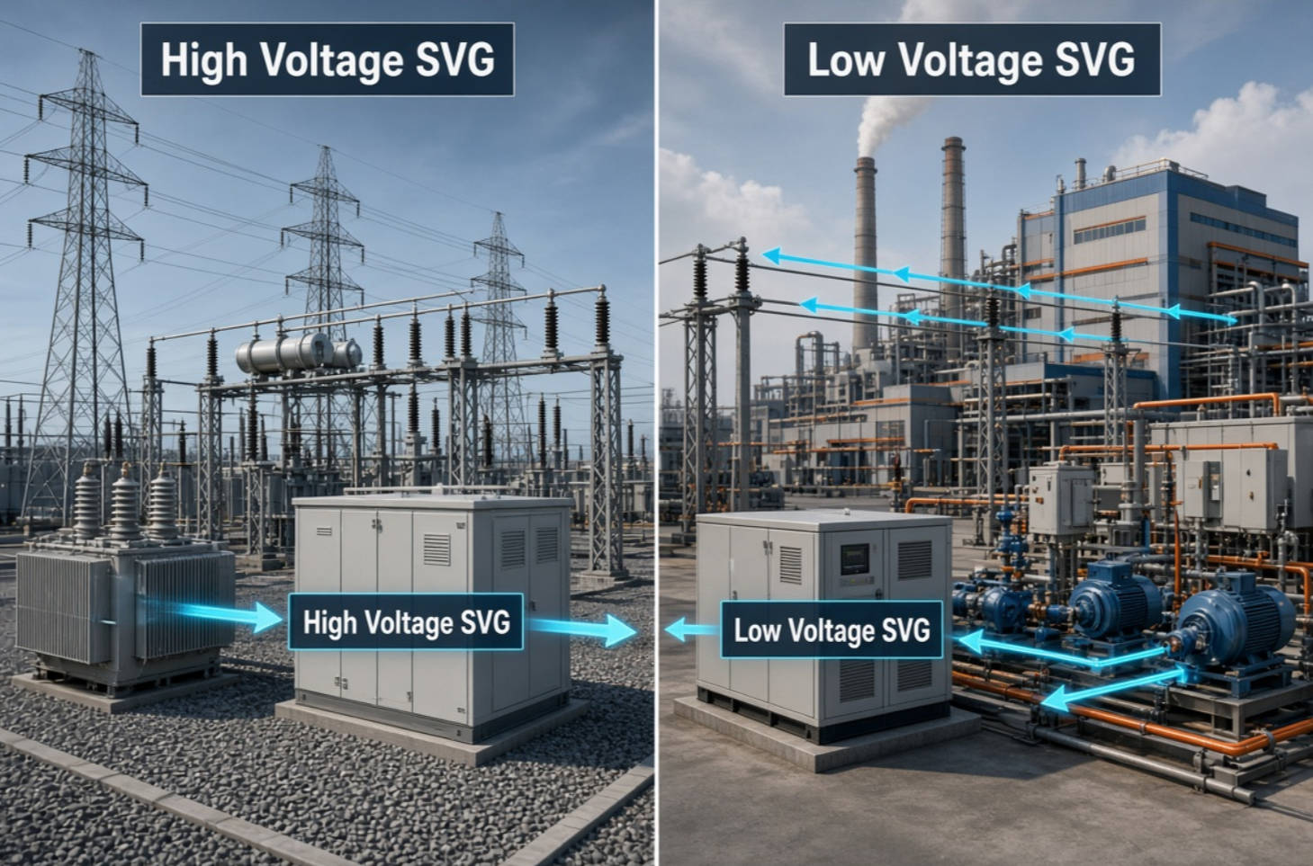
The most important difference is the point of electrical connection.
A high voltage SVG is connected directly to a high-voltage or transmission-level bus, usually through an interface transformer. A low voltage SVG is installed at a lower-voltage bus, feeder, industrial distribution system, or large-load connection point.
The selected voltage level changes the physical scale of the installation, Mvar capacity, protection design, insulation coordination, harmonic assessment, control objective, and economic model.
| Comparison Factor | High Voltage SVG | Low Voltage SVG |
|---|---|---|
| Typical installation point | Transmission or high-voltage substation bus | Distribution bus, feeder, plant intake, or load-side bus |
| Primary purpose | Grid voltage stability and bulk reactive-power control | Local voltage regulation, power-factor correction, and load-side power-quality improvement |
| Typical capacity | Medium to very large Mvar ranges | Small to medium Mvar ranges, often modular |
| Electrical reach | Supports a wider network area | Delivers support close to the disturbance source |
| Interface requirement | Usually needs a dedicated coupling transformer and high-voltage switchgear | Can use lower-voltage switchgear and simpler integration in suitable projects |
| Main engineering focus | Grid-code compliance, transient performance, insulation, protection coordination | Load dynamics, feeder voltage drop, local harmonics, installation footprint |
| Best suited for | Transmission substations, renewable interconnection, weak-grid corridors, municipal grid projects | Industrial facilities, distribution substations, motor-intensive plants, localized voltage problems |
| Capital complexity | Higher | Usually lower, but depends on capacity and installation conditions |
A high voltage SVG is normally selected when the power-quality issue affects the substation bus or a broader grid area, rather than one downstream load.
For example, a utility may install a high voltage SVG at a 110 kV, 132 kV, 220 kV, or higher-voltage substation to stabilize voltage during changing generation output, line contingencies, light-load overvoltage, or heavy-load undervoltage conditions.
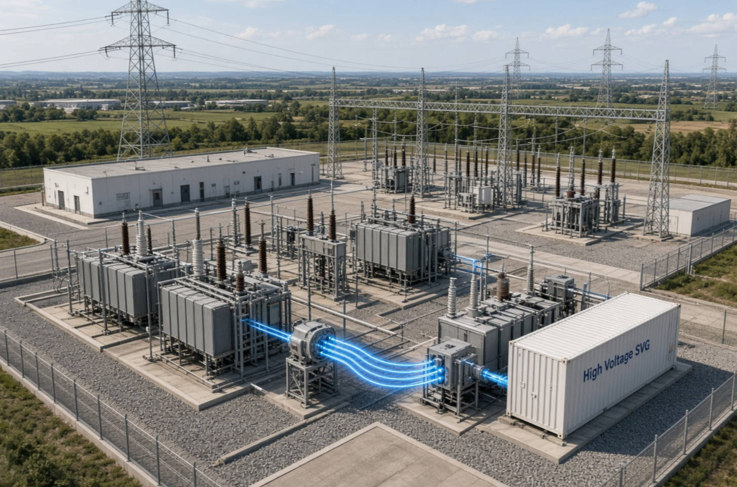
A high voltage SVG is often appropriate when a project involves:
- Long transmission corridors with high reactive-power demand
- Renewable-energy stations connected to a weak grid
- Voltage fluctuations after line switching or fault events
- Grid-code requirements for dynamic reactive-current injection
- Large industrial zones supplied by a common transmission substation
- Bulk voltage control for municipal or national infrastructure projects
- Excessive voltage rise during light-load operating periods
A high voltage installation can influence the network more broadly because it operates near the transmission bus. It is especially valuable when the utility needs voltage support where system strength is limited or where a disturbance can propagate across multiple substations.
High system-level impact. Reactive compensation is delivered near the bus that governs the wider network voltage profile.
Better support for grid stability. The SVG can respond dynamically to voltage deviations, helping maintain bus voltage after disturbances.
Suitable for large Mvar ratings. High voltage SVG projects are designed for substantial reactive-power demand and utility-scale operation.
Supports renewable integration. Wind and solar connections can create rapid active-power changes and voltage fluctuations. High voltage SVG systems can help keep the point of interconnection within voltage-control requirements.
Useful during low-voltage conditions. A converter-based STATCOM/SVG can provide strong capacitive reactive-current support during voltage depression, unlike a traditional capacitor-based approach whose reactive output reduces with voltage.
A high voltage SVG is not automatically the best solution for every power-quality issue.
It usually requires:
- More extensive civil works
- Dedicated high-voltage equipment
- Higher insulation and clearance requirements
- Advanced protection coordination
- A detailed grid study
- Larger initial investment
- Longer engineering, procurement, and commissioning cycles
Also, a high voltage SVG installed far from a problematic nonlinear load may improve transmission-bus voltage without fully resolving local feeder harmonics or plant-side voltage dips. Location matters as much as capacity.
A low voltage SVG is installed closer to the reactive-power demand or harmonic-producing load. It is commonly used at distribution voltage levels and in industrial electrical systems where voltage variation, poor power factor, flicker, or load imbalance originates near the consumer side.
For manufacturers in metallurgy, petrochemicals, automotive production, paper, textile, building-materials processing, and similar sectors, low voltage SVG solutions can address rapid load changes before they create wider disturbance in the upstream network.

A low voltage SVG is often the stronger option when the project includes:
- Large motor starts or frequent motor load variation
- Welding equipment and automotive production lines
- Arc furnaces, rolling mills, crushers, or mining equipment
- Variable-frequency drives and rectifier loads
- Textile, paper, cement, and chemical-process loads
- Localized voltage drops at a distribution bus
- Power-factor penalties or reactive-demand charges
- Expansion of an existing industrial electrical system
Compensation close to the load. This reduces the reactive current flowing through upstream transformers and cables.
Improved local voltage quality. A low voltage SVG can stabilize the bus supplying sensitive equipment.
Reduced electrical losses. Lower reactive current in distribution conductors can reduce I⊃2;R losses and release capacity in transformers and feeders.
Modular expansion. Many low voltage SVG designs can be scaled as production lines, loads, or plant capacity grow.
Practical retrofit option. For existing industrial sites, a low voltage SVG may be easier to integrate than a high-voltage solution.
Fast response to fluctuating loads. This is important where traditional capacitor banks cannot follow rapid demand changes without excessive switching operations.
Low voltage SVG systems have a more localized effect. They may not solve a transmission-level voltage-stability issue, and several units may be needed across a large facility or multi-feeder network.
They also require careful harmonic and resonance assessment. An SVG improves reactive-power control, but it is not a substitute for a proper harmonic study. Where substantial harmonic current exists, the project may require coordinated active filtering, passive filtering, detuned capacitor design, or harmonic mitigation at the source.
The right choice depends on the electrical problem location, not merely on the nominal voltage printed on the substation drawing.
Start with the question: what must be controlled?
- If the objective is to stabilize a transmission or sub-transmission bus, choose a high voltage SVG architecture.
- If the objective is to correct power factor and voltage at an industrial load center, assess a low voltage SVG.
- If both problems exist, a coordinated high-voltage and low-voltage compensation strategy may be justified.
For example, a 110 kV utility substation feeding a steel plant may need high voltage SVG support for network voltage stability. The steel plant may also need a low voltage SVG or active harmonic filter near its electric arc furnace or rolling-mill bus. One device cannot always solve both problems efficiently.
Do not size SVG capacity based only on historical power-factor data.
Review:
- Maximum and minimum Mvar demand
- Rate of reactive-power change
- Voltage deviation range
- Fault and post-fault voltage behavior
- Load ramp patterns
- Transformer loading
- Renewable-generation variability
- Future expansion plans
A system that appears acceptable in average conditions may become unstable during a short circuit, motor restart, furnace cycle, or generation ramp. The SVG must be rated for the operating scenario that matters most, not just the normal average load.
A weak grid is more sensitive to reactive-power changes. In these projects, the SVG control system, voltage droop setting, response characteristics, and fault ride-through behavior become critical.
For weak-grid renewable interconnection, a high voltage SVG may provide the dynamic voltage support needed at the point of common coupling. For a weak industrial feeder, a low voltage SVG may prevent local voltage dips and improve equipment reliability.
Harmonic compliance should be assessed at the point of common coupling (PCC). This is essential where converters, variable-frequency drives, rectifiers, furnaces, UPS systems, or renewable inverters are present.
A complete study should examine:
- Existing voltage and current harmonic levels
- Harmonic spectrum by order
- System impedance across operating states
- Resonance risk
- Capacitor-bank interaction
- Transformer and cable heating
- PCC harmonic targets
- Required filter coordination
IEEE 519 provides widely used guidance for harmonic control in systems containing nonlinear loads. In practical engineering, the final design should use site measurement, network modelling, and applicable local utility requirements rather than applying a generic harmonic limit without context.
| Project Condition | Recommended Priority | Why |
|---|---|---|
| 110 kV or higher bus voltage instability | High voltage SVG | Direct support at the affected utility bus |
| Wind or solar plant grid connection | High voltage SVG | Dynamic voltage control at the interconnection point |
| Factory has poor power factor and fluctuating motor loads | Low voltage SVG | Local reactive compensation reduces upstream current |
| Arc furnace or rolling mill causes rapid voltage fluctuation | Low voltage SVG, possibly combined with HV SVG | Local control handles the load disturbance; HV support may protect the wider grid |
| Light-load overvoltage at a transmission substation | High voltage SVG | Inductive reactive absorption at the transmission bus |
| Multiple distribution feeders have separate issues | Distributed low voltage SVG units | Better compensation at individual load centers |
| New major utility substation project | High voltage SVG feasibility study | Evaluate system-wide voltage stability and grid-code needs |
| Existing plant retrofit with space constraints | Low voltage modular SVG | Easier staged installation in many cases |
Before purchasing an SVG system, utilities and EPC contractors should prepare a technically complete specification.
1. Confirm the installation bus voltage and voltage operating range
2. Define the required capacitive and inductive Mvar range
3. Specify response time and control modes, including voltage control, reactive-power control, and power-factor control
4. Provide short-circuit level and network impedance data
5. Identify harmonic sources and existing capacitor banks
6. Clarify grid-code and utility compliance requirements
7. Define ambient temperature, altitude, pollution level, seismic requirements, and enclosure requirements
8. Require protection, communication, SCADA, and cybersecurity interfaces
9. Request factory testing, site acceptance testing, commissioning support, and training
10. Evaluate lifecycle service capability, spare parts, remote diagnostics, and maintenance access
A strong supplier should not only quote Mvar capacity. The supplier should also demonstrate how the SVG will behave under actual voltage conditions, load changes, harmonic exposure, and protection events.
In our experience with reactive-power compensation and harmonic-control projects, the strongest outcomes come from treating the SVG as part of a complete electrical system.
The final performance depends on:
- Transformer impedance
- Cable and line configuration
- Existing capacitor banks
- Harmonic background levels
- Switching sequence
- Load operating cycles
- Protection settings
- Metering location
- Control coordination with OLTC transformers, capacitor banks, reactors, and renewable inverters
A well-designed low voltage SVG can provide excellent local power-factor correction but may have limited impact on an unstable remote transmission bus. A properly rated high voltage SVG can stabilize a utility network but may not eliminate harmonic distortion generated deep inside an industrial plant.
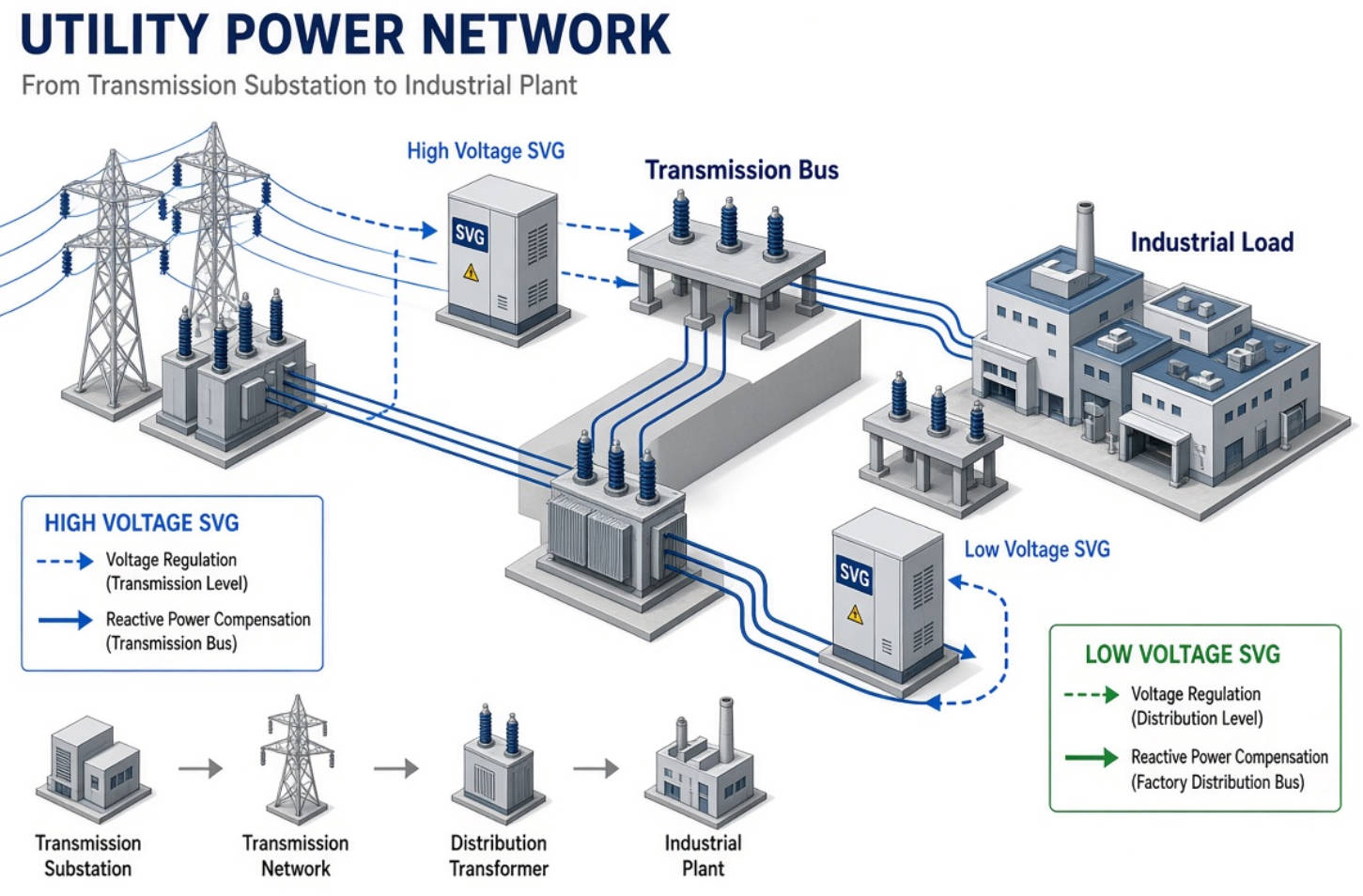
The best technical decision is often a layered one: use high voltage SVG for grid-level voltage stability and low voltage SVG for load-side power quality and reactive-current reduction.
The decision between high voltage SVG vs low voltage SVG for utility substations should be based on where the voltage problem originates, where reactive support produces the greatest benefit, and how the system performs during dynamic or fault conditions.
Choose a high voltage SVG when you need large-scale, dynamic voltage support at a transmission or utility substation bus. Choose a low voltage SVG when you need fast, localized power-factor correction and voltage stabilization near industrial loads. For complex utility-industrial networks, combine both levels in a coordinated power-quality strategy.
DINGNUO ELECTRIC CO., Ltd. provides reactive-power compensation and harmonic-control solutions for industrial facilities, utility substations, and key municipal infrastructure projects. Contact our engineering team to discuss your single-line diagram, load profile, harmonic measurements, Mvar requirement, and substation voltage level. We can help you evaluate the most suitable SVG configuration for stable, efficient, and compliant power-system operation.
The main difference is the connection point. A high voltage SVG operates at a utility or transmission-level bus to support broader grid voltage stability. A low voltage SVG operates closer to industrial loads or distribution feeders to improve local voltage, power factor, and feeder efficiency.
Usually, no. A low voltage SVG can solve local reactive-power and voltage-quality issues, but it may not provide sufficient voltage support at a remote high-voltage substation bus. The required solution depends on the location and scale of the electrical problem.
A high voltage SVG is commonly preferred at the renewable-energy point of interconnection because it can provide dynamic reactive-power control at the utility bus. The final selection should be based on grid strength, grid-code requirements, voltage range, and fault ride-through studies.
An SVG primarily manages reactive power and voltage. Depending on converter design and application, it may have good harmonic performance, but it should not be assumed to solve all existing harmonic issues. Sites with significant nonlinear loads require harmonic measurement and a coordinated mitigation design.
SVG capacity should be sized using measured and modelled system data, including peak Mvar demand, voltage deviations, rate of load changes, short-circuit capacity, future expansion, harmonic conditions, and fault-related voltage requirements. Do not size it from average power factor alone.
Yes. A high voltage SVG can operate in an inductive mode to absorb reactive power, helping control overvoltage that may occur during light-load conditions or when long transmission lines generate excess reactive power.
Yes. Low voltage SVG systems are widely applicable to industrial loads with fluctuating reactive-power demand, such as rolling mills, arc furnaces, crushers, pumps, compressors, variable-frequency drives, and high-capacity production lines. The application should be verified through load and harmonic analysis.
1. IEEE Standards Association. "[IEEE 519-2022: Standard for Harmonic Control in Electric Power Systems]"
2. IEEE Standards Association. "[IEEE 519: Harmonic Control in Electric Power Systems]"
3. EirGrid. "[Technical Specification: Static Synchronous Compensator (STATCOM)]"
4. CIGRÉ US National Committee. "[STATCOM Application to Address Grid Stability and Reliability Requirements]"
5. CIGRÉ US National Committee. "[Dynamic Voltage Support at a 115 kV System: Colington STATCOM]"
6. CIGRÉ US National Committee. "[Installation and Commissioning of MMC STATCOM Systems at 500 kV Substations]"
7. Springer Reference Work. "[Technical Description of Static Compensators (STATCOM)]"


