
Views: 269 Author: Dingnuo Electric Publish Time: 2026-09-05 Origin: Site


Content Menu
● What Are Harmonics in Electrical Power Systems?
● Why Harmonic Mitigation Matters for Industrial Facilities
>> The Main Effects of Harmonic Distortion
>> Harmonics Are a Reliability Issue, Not Only a Compliance Issue
● Harmonic Assessment: Start with Measurement, Not Equipment Selection
>> Key Measurements to Collect
>> A Practical Four-Step Investigation Process
● Harmonic Mitigation Techniques: Choosing the Right Solution
>> Line Reactors and DC Chokes
>> Detuned Reactors and Harmonic-Safe Capacitor Banks
>> Hybrid Harmonic Mitigation Systems
● How to Prevent Resonance in Capacitor Compensation Systems
>> Warning Signs of Harmonic Resonance
>> Engineering Rules for Safer Compensation
● Industry Applications for Harmonic Control Solutions
>> Metallurgy and Heavy Industry
>> Petrochemical and Process Plants
>> Paper, Textile, and Building Materials
>> Municipal Infrastructure Projects
● Expert Checklist for Selecting a Harmonic Mitigation Solution
● Build a More Reliable Power System with DINGNUO ELECTRIC
>> 1. What is the difference between THD and TDD?
>> 2. Can a conventional capacitor bank increase harmonic problems?
>> 3. When should an active harmonic filter be used?
>> 4. Which harmonic orders are most common in industrial facilities?
>> 5. Can detuned reactors improve both power factor and harmonic reliability?
>> 6. How long should harmonic monitoring be performed?
>> 7. Do harmonic filters need maintenance?
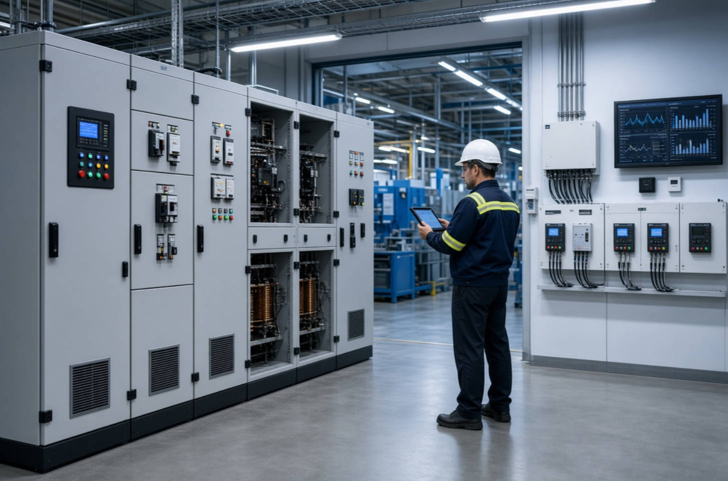
Industrial facilities are under growing pressure to maintain stable, efficient, and compliant electrical systems. As variable frequency drives, rectifiers, welding equipment, UPS systems, automation controllers, and other non-linear loads become more common, harmonic distortion has become one of the most persistent power-quality challenges in modern plants.
For manufacturers in metallurgy, petrochemicals, automotive, paper, textile, building materials, and municipal infrastructure, harmonics are not simply a technical measurement on a power-quality analyzer. They can contribute to overheating transformers, capacitor failures, nuisance trips, production interruptions, motor stress, inaccurate metering, and increased maintenance costs.
DINGNUO ELECTRIC CO., Ltd. provides capacitors, reactors, reactive power compensation equipment, and harmonic-control solutions designed for demanding industrial power systems. This guide explains the most effective harmonic mitigation techniques, how to select the right solution, and how to build a long-term power-quality strategy for complex industrial loads.
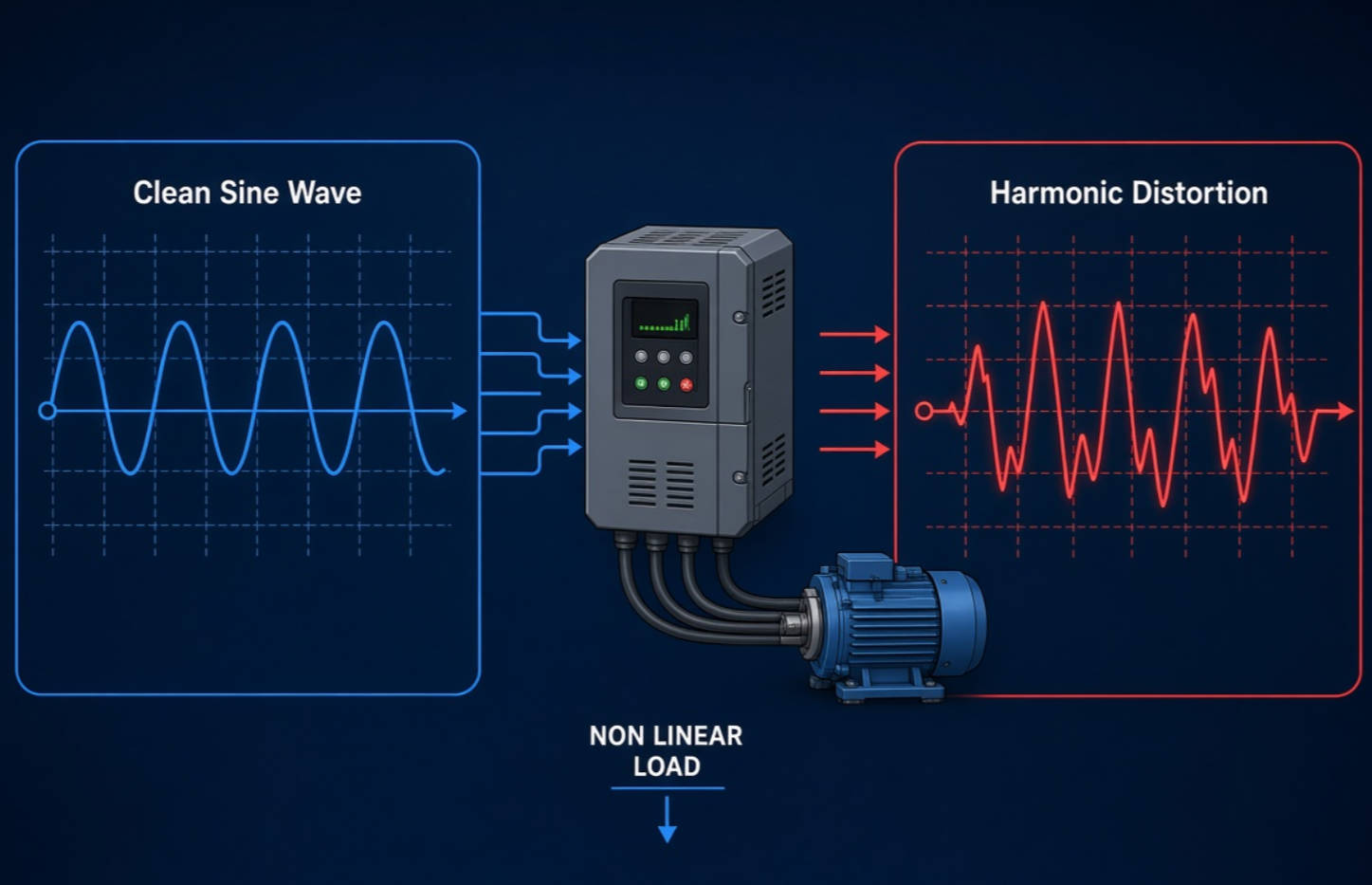
Electrical harmonics are voltage or current components whose frequencies are integer multiples of the fundamental system frequency.
In a 50 Hz system, for example:
- The 1st harmonic is the 50 Hz fundamental frequency.
- The 3rd harmonic is 150 Hz.
- The 5th harmonic is 250 Hz.
- The 7th harmonic is 350 Hz.
- The 11th harmonic is 550 Hz.
In an ideal electrical system, voltage and current waveforms are smooth sine waves. In real industrial networks, non-linear loads draw current in pulses rather than in a smooth sinusoidal pattern. These distorted currents travel through the electrical network and create voltage distortion when they interact with system impedance.
Common harmonic-producing loads include:
- Variable frequency drives (VFDs)
- Variable speed drives (VSDs)
- AC and DC motor drives
- Rectifiers and converters
- Uninterruptible power supply (UPS) systems
- Arc furnaces and welding machines
- Switch-mode power supplies
- LED lighting drivers
- Battery-charging systems
- Solar inverters and energy-storage converters
- CNC machines and automated production equipment
The growth of industrial electrification and digital automation has made harmonic management a more important part of power-system design. Non-linear loads can introduce harmonic currents that increase voltage distortion, reduce equipment efficiency, and create operational risks in low-voltage and medium-voltage networks.
Harmonics can affect almost every part of an electrical distribution system. The problem may appear slowly as higher operating temperatures and shortened component life, or suddenly as capacitor-bank failures, relay misoperation, or unexplained trips.
Transformer overheating
Harmonic currents increase copper losses, eddy-current losses, and stray losses in transformers. A transformer designed for sinusoidal loading may run hotter when supplying a large amount of non-linear load.
Capacitor-bank failure
Conventional capacitor banks can attract harmonic currents because capacitor reactance decreases as frequency rises. Without properly selected detuned reactors or harmonic filters, harmonic amplification and resonance can overload capacitors.
Motor losses and vibration
Harmonic voltage can produce extra losses, torque pulsation, noise, heating, and vibration in motors. This is especially relevant in plants that rely on pumps, fans, compressors, conveyors, and high-duty-cycle production machines.
Cable and neutral conductor overheating
Triplen harmonics, especially the 3rd harmonic and its multiples, can add in the neutral conductor of three-phase, four-wire systems. This can create neutral currents higher than expected from the phase-current loading.
Nuisance tripping and control-system faults
Harmonic distortion can interfere with sensitive protection relays, PLCs, sensors, controllers, metering devices, and communication systems. In automated facilities, even a brief control fault can have an outsized impact on production.
Poor power factor correction performance
A standard capacitor bank may improve displacement power factor while worsening harmonic conditions if resonance is not evaluated. Effective reactive power compensation must account for both power factor and harmonic behavior.
Many project teams focus on harmonic limits only when a utility connection agreement, customer requirement, or audit demands it. However, the strongest business case for mitigation is usually reliability.
A facility that reduces excessive harmonic stress may gain:
- Longer transformer, capacitor, and cable service life
- Fewer unexpected shutdowns
- More stable production processes
- Lower reactive-power penalties where applicable
- Improved energy-system visibility
- Easier expansion of drives, automation equipment, and renewable-energy assets
- Better alignment with applicable power-quality requirements
IEEE 519 provides recommended practices for managing harmonic voltage and current distortion at the point of common coupling, while IEC 61000-2-4 addresses compatibility levels for low-frequency disturbances in industrial installations up to 35 kV.
The most common mistake in harmonic mitigation is selecting equipment before understanding the facility's harmonic profile. A capacitor bank, detuned reactor, passive filter, active harmonic filter, or hybrid solution should be selected based on measured data and system analysis—not only on the size of the connected load.
A professional harmonic assessment should consider the electrical system as a whole.
A power-quality study should normally measure:
- Voltage total harmonic distortion, or THDv
- Current total demand distortion, or TDD
- Current total harmonic distortion, or THDi
- Individual harmonic orders, such as the 3rd, 5th, 7th, 11th, and 13th
- Voltage and current unbalance
- True power factor and displacement power factor
- Load demand profile by shift, day, and production state
- Transformer loading and temperature conditions
- Capacitor-bank operating status
- Utility short-circuit capacity at the point of common coupling
- Background harmonic distortion from the upstream system
- Existing reactors, filters, drives, UPS systems, and renewable-energy inverters
Important: THDi alone does not always show the full system risk. A current waveform can have high THDi at light load but contribute relatively little harmonic current in amperes. For utility and system-compliance evaluations, TDD is often more relevant because it relates harmonic current to maximum demand current.
1. Map the electrical system.
Identify transformers, feeder panels, capacitor banks, large drives, rectifiers, UPS systems, generators, and sensitive loads.
2. Measure under real operating conditions.
Record data during normal production, high-load periods, start-up, shift changes, and major process variations. A short measurement during low production may produce misleading results.
3. Identify the dominant harmonic sources.
Determine whether distortion comes mainly from six-pulse drives, twelve-pulse rectifiers, welding loads, single-phase electronic loads, inverters, or external network conditions.
4. Model possible mitigation options.
Evaluate resonance, capacitor switching, future expansion, load diversity, target harmonic levels, and economic requirements before finalizing the design.
There is no single harmonic mitigation technique that suits every facility. The best solution depends on the load profile, voltage level, dominant harmonic orders, required power factor, network impedance, existing equipment, and expected future expansion.
| Harmonic mitigation technique | Best suited for | Key strengths | Main design consideration |
|---|---|---|---|
| Line reactors | Individual drives and converters | Low-cost reduction of current distortion; limits inrush and protects drives | Does not provide broad system-level harmonic control |
| DC link chokes | VFDs and rectifier-fed equipment | Reduces harmonic current at the drive level | Must be compatible with drive design and loading |
| Detuned capacitor banks | Facilities needing power factor correction with harmonic risk | Provides reactive power compensation while reducing resonance risk | Requires correct reactor tuning and capacitor selection |
| Passive harmonic filters | Predictable, stable harmonic spectrum | Can target specific harmonic orders effectively | Risk of detuning, overload, or resonance if the system changes |
| Active harmonic filters | Dynamic and variable non-linear loads | Real-time compensation for multiple harmonic orders | Requires correct current rating, installation point, and control settings |
| Hybrid harmonic filters | Plants requiring both reactive power and harmonic control | Combines passive and active benefits | Needs coordinated engineering and lifecycle planning |
| Phase-shifting transformers | Large multi-pulse rectifier systems | Can cancel characteristic harmonics at the source | More suitable for specific large-load configurations |
Line reactors and DC link chokes are practical first-line solutions for individual VFDs and rectifier loads. They add impedance to the circuit, helping smooth current waveforms and reduce harmonic-current peaks.
They are often appropriate when:
- A facility has many small or medium VFDs.
- The harmonic problem is localized.
- Drive protection and inrush-current reduction are also important.
- A cost-effective improvement is needed before considering system-level filtering.
However, reactors are not a complete solution for a large industrial plant with multiple non-linear loads. They reduce distortion from individual devices but may not bring the overall system to a target harmonic-performance level.
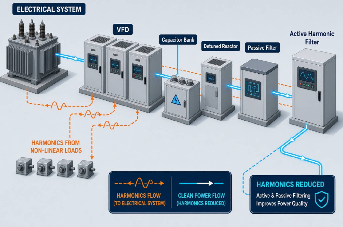
Reactive power compensation is essential for many industrial customers, but conventional capacitor banks can become vulnerable in harmonic-rich networks. Capacitors may resonate with transformer and system inductance, causing amplified harmonic currents and severe thermal stress.
A detuned capacitor bank combines capacitors with series reactors. The reactor shifts the system's resonant frequency below a critical harmonic order, helping prevent the capacitor bank from absorbing excessive harmonic current.
Detuned capacitor banks are particularly useful for:
- Manufacturing plants with VFD-driven motors
- Textile and paper production lines
- Automotive production facilities
- Commercial and industrial buildings with UPS systems
- Municipal pumping stations
- Facilities with fluctuating reactive-power demand
The correct tuning frequency must be determined through engineering analysis. Selecting a reactor only by a generic percentage value without considering the actual harmonic spectrum, transformer impedance, and capacitor capacity can create new risks rather than solve the original problem.
Passive filters use combinations of capacitors, reactors, and resistors to provide a low-impedance path for selected harmonic frequencies. They are often designed to absorb dominant harmonic currents, such as the 5th or 7th harmonic from six-pulse drive systems.
Passive filters work best when:
- Harmonic sources are stable and well understood.
- The plant load profile does not change dramatically.
- A particular harmonic order dominates.
- The facility needs reactive-power support in addition to harmonic filtering.
- The electrical network has been modeled carefully.
The main limitation is that passive filters are tuned solutions. If production changes, new drives are installed, transformer capacity is upgraded, or capacitor-bank configuration changes, the original filter design may no longer perform as expected.
An active harmonic filter (AHF) measures load current in real time and injects compensating current to reduce unwanted harmonic components. Unlike a passive filter, an AHF can adapt to changing load conditions and compensate multiple harmonic orders within its designed operating range.
Active harmonic filters are often the preferred solution when a facility has:
- Rapidly changing loads
- Multiple VFDs with different operating patterns
- UPS systems and data-sensitive controls
- Robotic production equipment
- Electric vehicle charging infrastructure
- Renewable-energy inverters
- A mixture of harmonic sources that cannot be solved with one tuned passive filter
- Limited space for large passive-filter assemblies
An AHF can also be configured to support reactive-power compensation and load balancing, depending on the system design and product capability. The key engineering question is not simply "How many amps should the filter be?" It is "Where should it be installed, what harmonic spectrum must it address, and how much compensating current is required during the plant's highest-risk operating condition?"
A hybrid solution combines passive and active technologies. For example, a detuned capacitor bank or passive filter can provide bulk reactive-power compensation and address stable harmonic components, while an active harmonic filter handles changing residual harmonics.
This approach can be especially effective for large industrial facilities where:
- Reactive-power demand is high.
- Harmonic sources vary by production stage.
- Space and investment need to be optimized.
- A plant needs a scalable design for future capacity expansion.
- Compliance and operational reliability are both priorities.
Resonance is one of the most serious risks in industrial power factor correction. It occurs when the inductive reactance of the electrical system and the capacitive reactance of a capacitor bank interact at or near a harmonic frequency.
When resonance occurs, a normally manageable harmonic current can be amplified. The result may include capacitor overheating, blown fuses, swollen capacitor cases, tripped breakers, damaged contactors, and repeated production interruptions.
Watch for the following symptoms:
- Repeated capacitor fuse failures
- Capacitor-bank overheating
- Excessive current in capacitor branches
- Audible noise from reactors or transformers
- Voltage THD that increases after capacitor switching
- Harmonic levels that change sharply when compensation stages connect
- Frequent power-factor-controller alarms
- Unexplained breaker trips in low-voltage distribution boards
- Do not install standard capacitor banks in a harmonic-rich facility without a harmonic study.
- Use capacitors specifically rated for the anticipated voltage and harmonic-current conditions.
- Select detuned reactors according to the measured harmonic spectrum and system parameters.
- Check capacitor switching sequences and controller settings.
- Consider future additions of drives, inverters, and other non-linear loads.
- Measure harmonic conditions again after commissioning.
- Monitor capacitor temperature, current, and voltage as part of preventive maintenance.
Harmonic mitigation should be linked to the production process, not treated as a generic electrical upgrade. Each industry has a different combination of load behavior, operating cycle, and reliability requirement.
Metallurgical plants may operate large motors, rolling mills, rectifiers, furnaces, welding equipment, and high-capacity drives. These loads can create high current distortion and rapid load changes.
A typical solution may include detuned reactive-power compensation for bulk kvar demand, combined with active harmonic filtering at critical low-voltage distribution points.
Petrochemical facilities often depend on uninterrupted operation of pumps, compressors, fans, process controls, and safety systems. Harmonic-related trips or control instability can create major operational and safety concerns.
Priority areas include reliable capacitor-bank design, harmonic monitoring at main switchboards, and filtering near large variable-speed drive groups.
Automotive plants frequently use robotic welding, conveyors, stamping lines, machine tools, paint-shop systems, and automated assembly equipment. These production loads can change quickly across shifts and model cycles.
Active harmonic filters or hybrid power-quality systems can be effective because they adapt to variable production patterns while supporting power factor and system stability.
Paper machines, textile lines, crushers, kilns, extruders, fans, and pumps often depend heavily on VFD control. The combination of continuous operation and multiple motor-drive loads makes harmonic assessment essential before adding compensation capacitors.
A properly designed solution helps protect capacitors, stabilize voltage, and support reliable motor-drive operation during high-demand periods.
Water-treatment plants, pumping stations, rail systems, public facilities, and other municipal projects increasingly use automation, VFD-driven pumps, UPS systems, and digital control equipment. Harmonic mitigation improves electrical reliability in systems where downtime may affect public services.
Before specifying capacitors, reactors, active filters, or a complete power-quality system, ask these questions:
1. What are the dominant harmonic orders and their actual current levels?
2. What are the measured THDv, THDi, and TDD values at relevant connection points?
3. Is the facility experiencing capacitor failures, transformer heating, relay trips, or process instability?
4. What is the utility short-circuit capacity and transformer impedance?
5. Are capacitors already installed, and are they detuned?
6. Are harmonic sources stable, intermittent, or rapidly variable?
7. Does the project require only harmonic reduction, or also reactive-power compensation and load balancing?
8. What future drives, inverters, production lines, or renewable-energy systems are planned?
9. What target performance level is required at the point of common coupling?
10. Who will commission, verify, monitor, and maintain the solution after installation?
A high-quality project should end with a documented commissioning report. The report should compare pre-installation and post-installation measurements, confirm equipment settings, and establish a baseline for future maintenance.
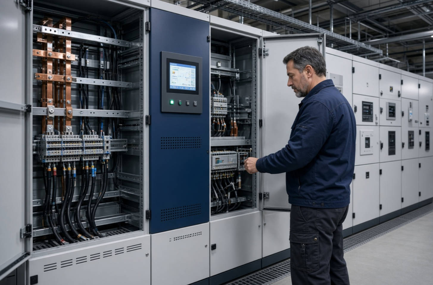
Harmonic mitigation is most effective when it is treated as part of an integrated power-quality strategy. The right solution begins with measurement, continues with system-specific engineering, and ends with verified commissioning performance.
DINGNUO ELECTRIC CO., Ltd. supports customers with advanced capacitor and reactor technologies, reactive power compensation equipment, harmonic-control solutions, and comprehensive technical service. Whether your project involves metallurgy, petrochemicals, automotive manufacturing, paper production, textile machinery, building materials, or a critical municipal facility, our engineering team can help evaluate your power-quality challenges and develop a practical solution.
Contact DINGNUO ELECTRIC today to discuss your harmonic measurement data, capacitor-bank requirements, reactive-power targets, and power-quality improvement goals. A properly designed solution can protect critical equipment, improve operational stability, and prepare your facility for future electrification and automation.
THD measures harmonic distortion relative to the present fundamental value. TDD measures harmonic current relative to the maximum demand current of the system. For harmonic-current evaluation at a facility connection point, TDD is often more useful because it reflects distortion against the site's demand capacity.
Yes. A conventional capacitor bank can interact with network inductance and create resonance. This may amplify harmonic currents, overload capacitors, and increase voltage distortion. In harmonic-rich systems, a detuned capacitor bank or engineered filtering solution is usually safer.
An active harmonic filter is especially suitable for facilities with variable loads, multiple VFDs, UPS systems, automation equipment, robotic systems, inverter-based resources, or multiple harmonic orders. It provides dynamic compensation rather than targeting only one fixed harmonic frequency.
The 5th and 7th harmonics are common in three-phase systems with six-pulse rectifiers and drives. The 3rd harmonic and other triplen harmonics are especially important in three-phase, four-wire systems with many single-phase electronic loads.
Yes. When installed with capacitor banks, detuned reactors help reduce resonance risk while allowing the system to provide reactive-power compensation. The reactor and capacitor ratings must be selected based on the actual electrical network and harmonic conditions.
Monitoring should cover representative operating conditions, including normal production, peak demand, load changes, shift changes, and significant process events. For facilities with variable operating patterns, several days or a full production cycle may provide more meaningful data than a short spot measurement.
Yes. Maintenance should include periodic inspection of filter current, capacitor condition, reactor temperature, cooling systems, switching devices, protective devices, controller settings, and harmonic performance. A post-installation baseline makes long-term maintenance more effective.
1. Eaton. "IEEE 519 Standard: What Do I Need to Know?"
2. IEC 61000-2-4:2024. "Electromagnetic Compatibility (EMC) — Part 2-4: Environment — Compatibility Levels in Industrial Plants for Low-Frequency Conducted Disturbances."
[https://www.evs.ee/en/iec-61000-2-4-2024]
3. Mirus International. "IEEE Std 519-2014 Harmonic Limits."
4. Wiley Energy Science & Engineering. "Impacts of Nonlinear Loads on the Power Quality of Solar Microgrids."
[https://scijournals.onlinelibrary.wiley.com/doi/full/10.1002/ese3.70019]
5. ScienceDirect. "Investigation of Harmonics Analysis in Power Systems Due to Nonlinear Loads."
[https://www.sciencedirect.com/science/article/pii/S2352484723015585]
6. Shanghai Yingtong Electric Co., Ltd. "Harmonics Mitigation Techniques Blog Archive."
[https://www.ytelect.com/blog/harmonics-mitigation-techniques_bk_3]


