


| Quantity: | |
|---|---|


High Voltage Parallel Capacitor With Built-in Fuse
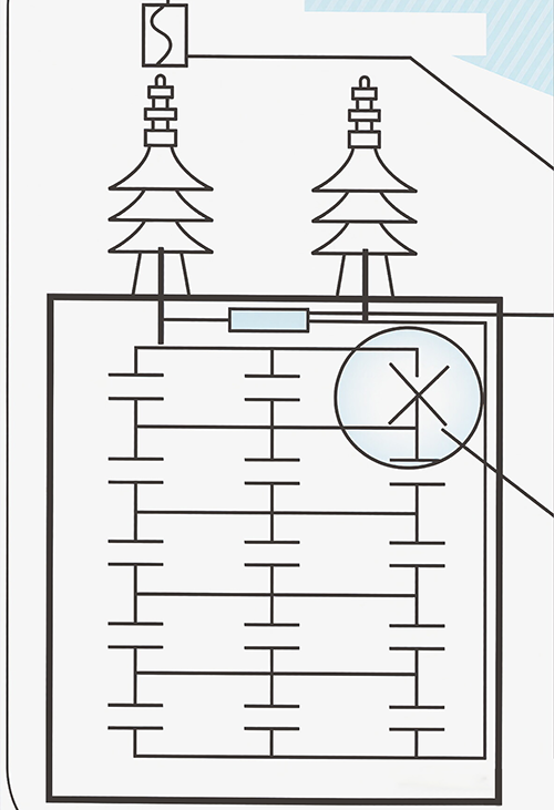
Internal fuse type can continue to operate after fuse action
When the small unit capacitor inside the capacitor fails, its internal fuse will quickly cut off and eliminate the fault point to continue operating.

Standard type (without built-in fuse);If the small unit capacitor inside the capacitor;fails and the external protection fuse is activat-
Item | Contains a fuse-type capacitor | Conventional capacitors |
Installation Space | Small | Big |
Reusability after small-unit operations | Great | Depends on situation |
Reactive power losses. | Low probability | Normal |
Unbalance protection | Great | Normal |
Fuse protection | Great | Normal |
Shell fragmentation | Low probability | Normal |
Possibility of fuse malfunction | Low probability | Normal |

Advantage:
Internal fuse type
When the fuse of each small unit capacitor is blown, its total capacity is only lost by the capacity of that small unit.
Small installation space
Equipped with a fuse type installation,it can be directly connected in n-type parallel with wires, greatly reducing installation space. It is particularly suitable for installation in panels and can save on distribution equipment costs.

Specifications And Performance
| Set the scene | Outdoor or indoor |
Environment Temperature | -20°C~+40°C(An average of 35°C or less over a 24-hour period) |
Operating Voltage | Rated voltage: 110% or less (24-hour average must be 110% or less) |
Maximum Operating Current | Rated current: 135% or less (including high harmonics and manufacturing tolerance) |
Capacitance Tolerance | Rated value: -5% to +10% (phase-to-phase error must be within 3%) |
Loss | Less than 0.35% at 20°C |
Temperature Rise | When the ambient temperature is below 40°C, the temperature rise is less than 25°C |
Compactness | After heating for 4 hours in a 80+5°C constant-temperature bath, no oil leakage was observed on the exterior of the capacitor. |
Discharge characteristics | Equipped with a discharge resistor; the residual voltage of the capacitor drops below 50 V within five minutes after the power is disconnected. |
Safety | Each individual capacitor in the unit is protected by its own fuse, ensuring excellent safety. |
specification standard | CNS1372, 3739, JIS C4902, IEC60871 |
Precautions For Use
Use an ambient temperature between-25°C and +40°C.
Do not carry the casing and do not use copper plates for parallel wiring.
When using two or more capacitors in parallel, please maintain a distance of at least 8cm between each capacitor to facilitate heat dissipation.
The sleeve and terminal should be kept clean to avoid insulation failure, and maintenance work must be carried out after cutting off the power supply for five minutes.
The harmonic content of the system should be considered, and the rated voltage of the capacitor should be increased to the withstand voltage level.
When it is an automatic power adjustment panel due to frequent switching times, Please use a series reactor for each section and increase the voltage withstand level of the capacitor.
To avoid damage to the capacitor caused by overlapping voltage, the capacitor should be disconnected and set for at least 5 minutes before being put back into operation.
Capacitors should be connected in series with reactors to suppress surge and harmonics.When connecting reactors in series, attention should be paid to the voltage rise of capacitors. Connect 6% reactors in series, with a 6.4% increase in capacitor voltage, Connect a 13% reactor in series,and increase the voltage of the capacitor by 15%.
This capacitor uses non flammable insulating oil. The internal fuse type complies with Article 436 of the Electrical Code, and each individual capacitor has individual fuse protection. However, for the traditional type (without internal fuse), please follow the electrical code regulations, and each individual capacitor should have individual fuse protection. Please strengthen safety and fire prevention.
Maintenance And Upkeep Of High-voltage Capacitors
Capacitors are suitable for ambient temperatures below 40°C. During initial installation, attention should be paid to whether the ambient temperature is table, whether the ventilation equipment is good, or whether the heat source radiation and ambient temperature rise occur. It is recommended that customers install capacitors in a well ventilated environment.
Attention should be paid to the contact situation of switches used in various protective devices for capacitors, as poor contact of switch contacts can cause fuse melting.
Check if the voltage and current used are normal. Over voltage causes an increase in capacitor capacity and temperature rise In addition to endangering the lifespan of capacitors, insulation damage to internal components is often caused by abnormal voltage.
Check the obstruction and casing of the capacitor. If oil leakage (including breakage) is found in the obstruction, it should be promptly covered and sent to the factory for repair. If oil leakage is found in the casing, it should be repaired in a timely manner to avoid insulation oil degradation caused by insufficient oil and prolonged moisture entering the interior of the capacitor.
Check whether there are sparks or abnormalities caused by poor contact between the capacitor terminals and wires, which often lead to fuse meting during operation.
Check for any other abnormal phenomena.
Clean the dust on the surface of the magnetic sleeve. When capacitors are installed indoors or outdoors, dust will accumulate on the surface of the sleeve over a long period of time. If they absorb moisture,it will cause poor insulation and leakage,and in severe cases, the protective equipment may trip. After the capacitor is disconnected from the power supply for more than5 minutes and discharged through the ground wire, the dust on the magnetic sleeve can be removed to avoid electric shock.
The insulation resistance measurement between T-C must be above 1000MΩ.
Capacitance Detection
After the capacitor is fully discharged (measured by direct reading capacity).
Measurement method
Measure U-V=a,V-W=b, U-W=c three times.
Total capacity=(a+b+c) X 2÷3.
Judgment: Actual measured capacity a=b=c (total capacity=capacity value indicated on the nameplate)
Single Phase 6350V High Voltage Tuned Internal Fuse Type Capacitor Size Table (Applicable To System Voltage 10KV 50Hz)
| Model | Capacity | Current | Diagram Type | dimension | Weight | ||||||
| Kvar | μF | A | B | C | D | E | F | ||||
| DNSC/100-6.35-1P | 100 | 7.894 | 15.8 | B | 340 | 130 | 450 | 686 | 200 | 150 | 31 |
| DNSC/150-6.35-1P | 150 | 11.84 | 23.6 | B | 430 | 150 | 450 | 686 | 200 | 150 | 45 |
| DNSC/200-6.35-1P | 200 | 15.79 | 31.5 | B | 530 | 150 | 450 | 686 | 200 | 150 | 55 |
| DNSC/250-6.35-1P | 250 | 19.74 | 39.4 | B | 630 | 170 | 450 | 686 | 300 | 150 | 71 |
| DNSC/300-6.35-1P | 300 | 23.68 | 47.2 | B | 630 | 190 | 450 | 686 | 300 | 150 | 78 |
Three Phase 12000V High Voltage Tuned Internal Fuse Type
Capacitor Size Table(Applicable To System Voltage 10KV 50HZ)
| Model | Capacity | Current | Diagram Type | dimension | Weight | ||||||
| Kvar | μF | A | B | C | D | E | F | ||||
| DNSC/100-12.0-3P | 100 | 2.21 | 4.8 | A | 430 | 150 | 300 | 536 | 150 | 150 | 32 |
| DNSC/150-12.0-3P | 150 | 3.316 | 7.2 | A | 430 | 150 | 450 | 686 | 150 | 150 | 45 |
| DNSC/200-12.0-3P | 200 | 4.421 | 9.6 | A | 530 | 150 | 450 | 686 | 200 | 150 | 53 |
| DNSC/250-12.0-3P | 250 | 5.526 | 12 | A | 630 | 150 | 450 | 686 | 250 | 150 | 62 |
| DNSC/300-12.0-3P | 300 | 6.631 | 14.4 | A | 630 | 170 | 450 | 686 | 250 | 150 | 71 |
Single Phase 12700V High Voltage Tuned Internal Fuse Type Capacitor Size Table (Applicable To System Voltage 20KV 50Hz)
| Model | Capacity | Current | Diagram Type | dimension | Weight | ||||||
| Kvar | μF | A | B | C | D | E | F | ||||
| DNSC/100-12.7-1P | 100 | 1.974 | 7.9 | B | 340 | 130 | 450 | 731 | 200 | 150 | 33 |
| DNSC/150-12.7-1P | 150 | 2.96 | 11.8 | B | 430 | 150 | 450 | 731 | 200 | 150 | 44 |
| DNSC/200-12.7-1P | 200 | 3.497 | 15.7 | B | 530 | 170 | 450 | 731 | 200 | 150 | 59 |
| DNSC/250-12.7-1P | 250 | 4.934 | 19.7 | B | 630 | 170 | 450 | 731 | 300 | 150 | 69 |
| DNSC/300-12.7-1P | 300 | 5.291 | 23.6 | B | 630 | 170 | 525 | 806 | 300 | 150 | 79 |
Three Phase 22000V High Voltage Tuned Internal Fuse Type
Capacitor Size Table(Applicable To System Voltage 20KV 50HZ)
| Model | Capacity | Current | Diagram Type | dimension | Weight | ||||||
| Kvar | μF | A | B | C | D | E | F | ||||
| DNSC/100-22.0-3P | 100 | 0.658 | 2.6 | A | 630 | 130 | 300 | 581 | 250 | 150 | 41 |
| DNSC/150-22.0-3P | 150 | 0.986 | 3.9 | A | 630 | 130 | 450 | 731 | 250 | 150 | 57 |
| DNSC/200-22.0-3P | 200 | 1.315 | 5.2 | A | 630 | 150 | 450 | 731 | 250 | 150 | 64 |
| DNSC/250-22.0-3P | 250 | 1.664 | 6.6 | A | 630 | 190 | 450 | 731 | 250 | 150 | 78 |
| DNSC/300-22.0-3P | 300 | 1.973 | 7.9 | A | 630 | 190 | 525 | 806 | 300 | 150 | 89 |
Calculation Coefficient Of Capacity Change
Of High-voltage Capacitor After Voltage Increase
| System voltage(KV) | The rated voltage of the capacitor is to be increased(KV) | |||||||||||
| 3.45 | 3.8 | 4.0 | 4.16 | 4.6 | 4.8 | 11.95 | 12.8 | 13.8 | 23.9 | 25.4 | 27.5 | |
| 3.3 | 1.093 | 1.326 | 1.469 | 1.589 | 1.943 | 2.116 | - | - | - | - | - | - |
| 4.16 | - | - | - | - | 1.223 | 1.331 | - | - | - | - | - | - |
| 11.4 | - | - | - | - | - | - | 1.099 | 1.0261 | 1.465 | - | - | - |
| 22.8 | - | - | - | - | - | - | - | - | - | 1.099 | 1.241 | 1.455 |
Application Examples
12.8KV, Actual capacity conversion formula: The required capacitor capacity is calculated as follows: 100x1.261 (ac-cording to the table above)=126.1KVar
Assuming a system voltage of 11.4KV and a required capacitor capacity of 100Kvar, the rated voltage of the capacitor is
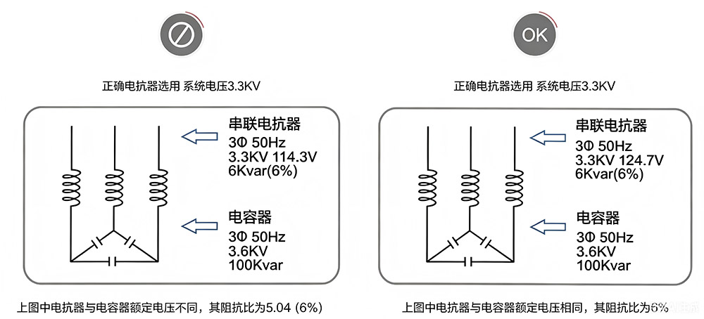
Calculation Of The Ratio Of Capacitive And Inductive Resistance

Hot Tags: Shunt Capacitor, Detuned Capacitor, China, private label, Customized, Bulk, discount, manufacturing company, suppliers, quotation


