
Views: 274 Author: Dingnuo Electric Publish Time: 2026-10-01 Origin: Site


Content Menu
● Why Injection Molding Loads Need a Closer Look
● Capacitor Bank vs APF: The Core Difference
● When a Capacitor Bank Makes Sense
>> The resonance check comes first
● A Worked Sizing Example—With Limits
● Measure Before You Specify: A Practical Workflow
● Cost, Savings, and Procurement Questions
● FAQ
>> 1. Is an APF better than a capacitor bank for every injection molding machine?
>> 2. Will a capacitor bank remove harmonics from servo-driven presses?
>> 3. Can one APF correct both harmonics and power factor?
>> 4. Does a high THDi reading at one drive mean the plant fails IEEE 519?
>> 5. Should capacitors be installed directly at a servo drive's output?
>> 6. What data should I send a supplier first?
Capacitor bank vs APF for injection molding machines is not simply a choice between two ways to improve power factor. A capacitor bank primarily supplies reactive power; an active power filter (APF) primarily cancels harmonic current. Some APFs can also compensate reactive current, but their available capacity and functions vary by model. The right choice depends on your molding machines' drive technology, measured electrical conditions, and utility requirements—not on a single power-factor reading.
For a plant with older constant-speed hydraulic machines, power-factor correction may be the main opportunity. For a plant dominated by servo-hydraulic or all-electric machines, drive-related harmonics may deserve closer attention. Mixed production lines can need both solutions. The practical starting point is to measure the plant through complete molding cycles before specifying either device.
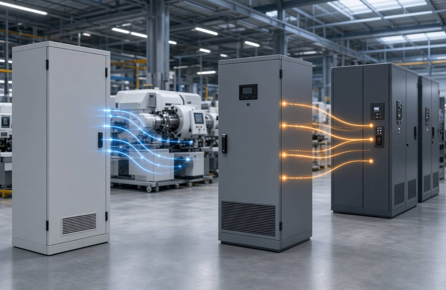
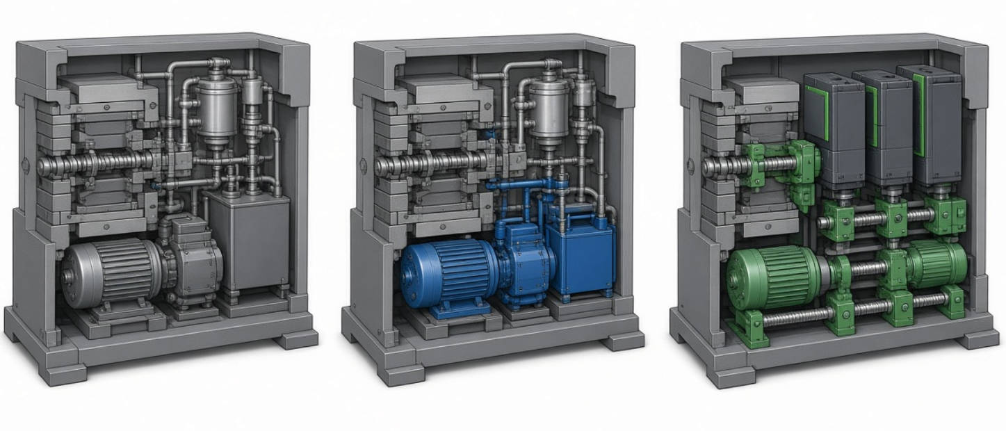
Injection molding equipment does not draw power in one unchanging way. Clamping, injection, plasticizing, cooling, and idle periods place different demands on the electrical system. Machine design matters too: a conventional hydraulic machine, a servo-driven hydraulic machine, and an all-electric machine use different motor and drive arrangements. An article by a Wittmann Battenfeld injection-molding specialist describes those distinctions and notes that energy use varies with the process.
That distinction changes the power-quality question:
- Constant-speed hydraulic machines may leave induction motors running through low-demand parts of a cycle. Their reactive-power demand can make capacitor-based correction valuable, subject to measurement.
- Servo-hydraulic machines use a servo motor to drive the hydraulic pump. Their electrical behavior must be assessed at the incoming supply, rather than inferred from the hydraulic function alone.
- All-electric machines use servo-electric drives for major movements. Their drive configuration makes harmonic measurement particularly relevant, although a drive-equipped machine should never be presumed noncompliant without testing.
The machine is also only part of the picture. A molding feeder may supply dryers, chillers, conveyors, and other auxiliary equipment. The correct compensation point therefore depends on whether the problem belongs to one machine, one production line, or the facility as a whole.
A capacitor bank supplies capacitive reactive power, usually specified in kilovolt-amperes reactive (kvar). By supplying some of an inductive load's reactive demand locally, it can reduce upstream current and apparent power. A fixed bank provides a relatively constant contribution; an automatic bank switches capacitor steps as demand changes. It is not, by itself, a general-purpose harmonic-cancellation device.
An APF—also called an active harmonic filter in many product descriptions—measures current and injects compensating current to counter selected harmonic components. Depending on its design and settings, it may also compensate fundamental-frequency reactive current and address phase imbalance. An APF must be sized for the functions it will perform at the same time.
| Decision factor | Capacitor bank | APF |
|---|---|---|
| Primary job | Correct inductive reactive-power demand | Reduce selected harmonic currents |
| Main sizing unit | kvar | Compensating amperes |
| Response to changing loads | Fixed output or switched steps | Electronic compensation that follows measured load changes |
| Harmonic treatment | A plain bank does not actively cancel harmonics | Injects counteracting harmonic current |
| Power-factor capability | Strong choice for sustained inductive kvar demand | Model-dependent; reactive-current compensation uses available capacity |
| Main application risk | Resonance, overstress, or overcorrection if poorly applied | Insufficient capacity, unsuitable settings, or incorrect sensing/placement |
| Best initial clue | Measured reactive demand and tariff exposure | Measured harmonic spectrum and a defined distortion objective |
These are functional distinctions, not guarantees of performance. A capacitor bank fitted with a series reactor is a detuned bank, not an APF. Detuning helps manage resonance risk; it does not mean that every harmonic problem has been removed. Conversely, an APF capable of power-factor correction does not automatically make a capacitor bank unnecessary when sustained kvar demand is large.
Choose capacitor-based correction when the principal finding is persistent inductive reactive-power demand and the harmonic study shows that the proposed installation is suitable. This may occur in a molding facility with conventional hydraulic drives, sizable induction-motor auxiliaries, or other inductive plant loads. The decision should reflect the utility's actual billing method: a low power factor matters financially when the applicable tariff imposes a relevant charge or limits usable capacity.
An automatic bank is often more appropriate than a fixed bank when presses, chillers, and other equipment cycle or operate on different shifts. Its controller can switch steps to follow changing reactive demand. Step size and control settings still matter: excessive correction during light-load periods can create an unwanted leading power factor.
Capacitors interact with the electrical system's inductance. Where harmonic-producing equipment is present, that interaction can create or worsen resonance near a significant harmonic frequency. A poorly selected bank may then experience excessive current or voltage instead of improving plant operation. ABB's application guidance treats capacitor selection, harmonic effects, filtering, switching, and protection as connected design questions—not separate purchases.
The engineering response is not "always add a reactor" or "never use capacitors." It is to review the measured spectrum, network characteristics, proposed kvar, and switching arrangement. A detuned capacitor bank may be appropriate where reactive compensation is needed and harmonic conditions make a plain bank unsuitable. Its reactor and capacitor ratings must be selected together.
An APF deserves priority when measured harmonic current—not merely a low displayed power-factor value—is the problem to solve. Rectifier-fed drives and other nonlinear equipment can distort current waveforms. An active filter senses the relevant components and injects opposing current. Its effectiveness depends on the harmonic orders present, required compensation current, operating conditions, installation point, and product capabilities.
For injection molding plants, the case may be strongest where several drive-equipped machines operate at changing loads, sensitive equipment shares distribution infrastructure, or a documented harmonic objective must be met. But do not buy an APF solely because an individual drive displays high current distortion. The facility's upstream measurements and applicable requirements determine whether correction is needed.
Also distinguish harmonic mitigation from voltage-event protection. An APF is not automatically a remedy for every brief voltage dip or interruption. If a production line stops during such events, capture event records before attributing the trips to harmonics. This protects the project from solving the wrong problem. Schneider Electric, for example, lists active filters and dynamic voltage restorers as different power-quality product types.
Yes. A detuned capacitor bank and an APF can serve different measured needs on the same site. The bank can address substantial fundamental-frequency reactive demand, while the APF targets selected harmonic currents that remain. ABB describes capacitor-based power-factor correction and active harmonic filtering as complementary approaches when properly engineered. Schneider Electric likewise lists industrial active-filter functions that include both harmonic mitigation and power-factor correction, illustrating why the required division of work must be specified rather than assumed.
A hybrid specification should answer four questions before equipment is ordered:
1. How much reactive compensation is required across normal and light-load conditions?
2. Which harmonic currents must be reduced, and at what operating points?
3. Could the proposed capacitor steps change the network's resonance behavior?
4. How will the APF prioritize harmonic and reactive-current compensation if both demands occur together?
The answers establish whether the plant needs one system, two coordinated systems, or a different remedy. They also prevent double-counting compensation capacity in a quotation.
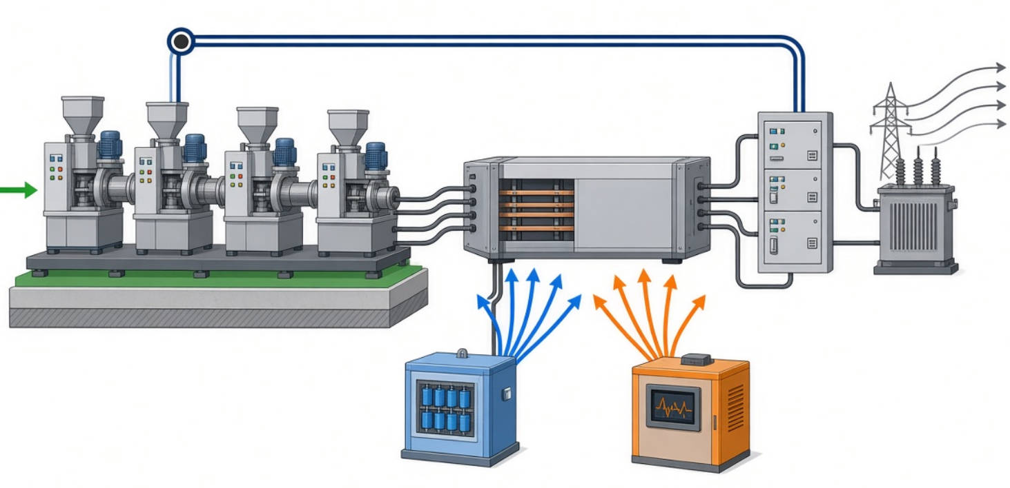
Suppose a molding feeder operates at 300 kW, and a suitable measurement shows a 0.80 displacement power factor at the condition being studied. The target is 0.95 displacement power factor. A first-pass capacitor estimate is:
Qc=P(tanϕ1−tanϕ2)
Using tanϕ1=0.75and tanϕ2≈0.329, the estimate is approximately 126 kvar. ABB presents this method for calculating reactive compensation under the relevant power-factor assumptions. It is a starting estimate, not a finished capacitor-bank design. Actual step selection must account for the load profile, voltage, existing compensation, harmonic conditions, and protection.
Now suppose the same feeder also has measurable harmonic current. The 126 kvar figure says nothing about APF ampere rating. That rating requires harmonic-current measurements, a target, and consideration of the highest relevant operating conditions. If the chosen APF will supply reactive current too, that duty must be included in its capacity assessment.
Most importantly, displacement power factor and true power factor are not interchangeable in a distorted system. Applying a simple capacitor formula to a single "PF" number without checking what the meter reports can lead to the wrong specification. Eaton explicitly separates its basic power-triangle explanation from its discussion of nonlinear, nonsinusoidal systems.
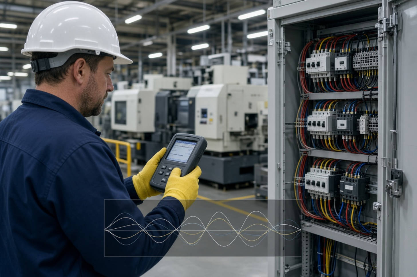
The most useful quote request is a measurement brief, not just a machine count. A power-quality engineer can use the following sequence to turn a broad "capacitor bank vs APF" question into a testable design:
1. Map the equipment. List molding-machine types, drive configurations, major auxiliaries, existing capacitors, transformers, and distribution points.
2. Review the bill and contract. Identify whether the utility charges for low power factor, reactive energy, apparent-power demand, or another relevant measure.
3. Measure at useful locations. Capture the service or point of common coupling (PCC) and the feeders where a solution may be installed.
4. Cover representative production. Include startup, high-output runs, cooling or idle intervals, shift changes, and combinations of machines that run together.
5. Record more than PF. Collect kW, kvar, true and displacement PF where available, current and voltage distortion, individual harmonic components, and the operating state associated with each reading.
6. Model and select. Check capacitor resonance and switching needs; assess APF compensating current, sensing arrangement, installation location, and simultaneous functions.
7. Verify after commissioning. Repeat the relevant measurements under comparable production conditions and check the agreed performance point.
IEEE 519-2022 describes steady-state voltage and current distortion limits at the user PCC for facilities containing harmonic-producing loads. It is not a blanket requirement that every individual molding machine or internal panel meet one universal distortion number. Any project target should state its measurement location and the applicable utility or contractual conditions.
A capacitor bank and an APF should not be compared only by purchase price. For a capacitor project, assess installed cost, switching and protection, potential tariff savings, upstream capacity benefits, and maintenance. For an APF, include its installation and operating requirements, the measured harmonic problem, and the value of meeting a documented performance objective. If both are proposed, evaluate them as a coordinated system.
Avoid promising a fixed percentage reduction in kWh consumption. Power-factor correction can reduce current and some upstream distribution losses, and a tariff may reward improved PF, but it does not make an injection press perform less mechanical or heating work by the same percentage. Eaton distinguishes bill savings produced by its example tariff from an actual reduction in energy consumed.
Request comparable supplier submissions that state the measurement basis, proposed location, capacitor kvar and step arrangement, detuning rationale where applicable, APF compensating-ampere rating, concurrent operating modes, exclusions, and post-installation verification method. These details make "better power quality" a measurable deliverable rather than a slogan.
For DINGNUO ELECTRIC CO., Ltd., the strongest closing proposition is an engineering review rather than an unconditional product claim: send your molding-line single-line diagram, machine and drive list, recent utility bills, and power-quality recordings to request a capacitor-bank, reactor, and APF application assessment. A recommendation can then be tied to the actual reactive demand, harmonic spectrum, and operating cycle.
No. A capacitor bank addresses reactive-power demand directly, while an APF addresses harmonic current and may offer additional compensation functions. "Better" depends on the measured problem and the APF model's capabilities.
A plain capacitor bank does not actively cancel harmonic currents. In a harmonic-rich system, its interaction with network inductance must be assessed before installation. A detuned bank manages a different design concern from an APF and should not be described as an equivalent replacement.
Some can, but not all products have identical functions. Confirm the model's operating modes and available compensating current when harmonic and reactive-current demands occur simultaneously.
Not necessarily. IEEE 519-2022 applies its steady-state distortion limits at the user PCC. An individual drive reading does not, on its own, establish facility-level compliance or noncompliance.
Do not treat a drive output like an ordinary utility-frequency motor supply. Any correction equipment associated with a drive must follow the drive manufacturer's instructions and an engineered installation design. The plant-level comparison in this article concerns properly selected compensation on the AC distribution system.
Send a single-line diagram, machine and drive inventory, operating schedule, utility tariff or bills, details of existing capacitor banks, and recordings of PF, kvar, and harmonics across representative cycles. These establish what should be corrected and where it should be measured.
1. IEEE Standards Association. [IEEE 519-2022: IEEE Standard for Harmonic Control in Electric Power Systems]. Official standard overview and PCC scope. [standards.ieee]
2. ABB. [Power Factor Correction and Harmonic Filtering in Electrical Plants]. Technical application paper covering kvar calculation, capacitor-bank arrangements, resonance, and filtering. [search.abb]
3. Eaton. [Power Factor Correction: A Guide for the Plant Engineer]. Guidance on power-factor correction, billing examples, installation choices, and harmonics. [eaton]
4. Schneider Electric. [Power Quality and Power Factor Correction]. Product-category descriptions distinguishing capacitor banks, active filters, and other power-quality equipment. [se]
5. Monolithic Power Systems. [Active Filters for Harmonic Elimination]. Explanation of compensating-current operation and sizing considerations. [monolithicpower]
6. Markus Klaus, Plastics Technology. [15 Things to Know About Servo-Driven Injection Machines]. Industry-specialist discussion of hydraulic, servo-hydraulic, hybrid, and all-electric architectures. [ptonline]
7. ARBURG. [Electric Injection Molding Machines]. Manufacturer description of servo-electric machine architecture. [arburg]


