
Views: 245 Author: Dingnuo Electric Publish Time: 2026-09-25 Origin: Site


Content Menu
>> Why a Brief Dip Stops Production
>> The Clue in the Event Pattern
● How to Diagnose Voltage Sags
● Which Mitigation Fits the Problem?
>> Check Equipment Immunity Before Buying
● Where Capacitors and Reactors Fit
● Turn Findings Into a Project Brief
● Build the Right Power-Quality Plan
● FAQ
>> 1. Is a voltage sag the same as a power outage?
>> 2. Can a capacitor bank eliminate voltage sags?
>> 3. What should we measure first?
>> 4. Should we protect the whole factory or one machine?
>> 5. Does a UPS always solve a voltage-sag problem?
>> 6. Can harmonic control and sag mitigation be specified together?
A voltage sag can last less than a second and still stop a production line. The supply does not have to fail completely: a brief drop can release a contactor, reset a controller, or trip a drive. For manufacturers, effective voltage sag mitigation starts with a precise question: Which component stopped first, and what did the voltage at that component actually do?
This guide explains how to measure voltage sags, trace their causes, and select protection for sensitive industrial loads. It also distinguishes sag protection from reactive power compensation and harmonic control—related power-quality disciplines that solve different problems.

A voltage sag, also called a voltage dip, is a temporary reduction in root-mean-square (RMS) voltage. A commonly used IEEE 1159 description places the remaining voltage between 10% and 90% of nominal for roughly half a cycle to one minute. Remaining voltage means the voltage still available during the event, not the amount lost. A 70% retained-voltage sag on a nominal 400 V system leaves approximately 280 V.
Sag depth alone does not predict whether equipment will trip. Engineers also examine duration, the phases affected, and—where relevant—the change in voltage phase angle. A brief, deep sag may disrupt one load, while a longer, shallower sag disrupts another. Three-phase equipment must be assessed across all relevant phase-to-phase or phase-to-neutral voltages, according to its connection and protection design.
The first component to fail is often not the largest motor. It may be a control power supply, undervoltage relay, contactor, or safety interlock. When that component drops out, an otherwise healthy process may stop.
EPRI testing of semiconductor tools illustrates the value of finding the weak link. In its published investigation, disturbances lasting as few as three cycles and retaining 93% of nominal voltage affected some tested tools. EPRI identified vulnerable emergency-off circuits and control power supplies, among other components. Those findings are specific to the equipment tested; they are not a universal trip threshold for industrial machinery.
For a paper mill, automotive line, textile plant, or petrochemical facility, the business consequence depends on the process. An electrical event lasting milliseconds may lead to much longer cleanup, restart, or quality-check work. That is why a useful investigation records both the electrical event and its production consequence.
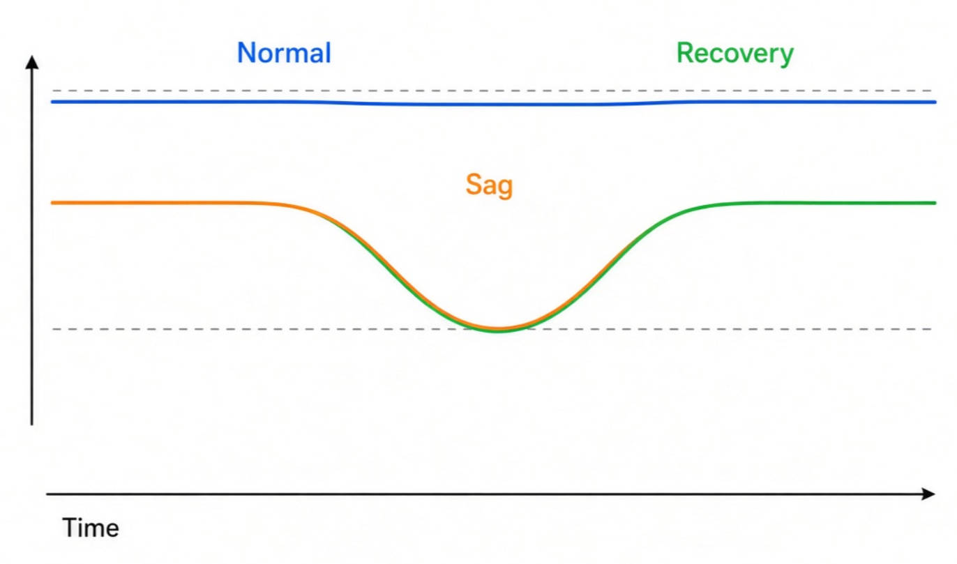
A sag can originate outside the facility or within its own distribution system. Distinguishing the two is essential: replacing equipment inside a plant will not remove an upstream fault, while blaming the utility will not fix a motor-starting problem on a shared plant bus.
- External faults: A fault on a utility feeder can pull down voltage at a neighboring facility while protective equipment clears it.
- Internal faults: A fault on one plant feeder can affect other loads connected through shared source impedance.
- Large motor starts: Starting current can temporarily depress voltage, especially on a relatively weak supply.
- Transformer energization: Inrush current can produce a short-duration voltage reduction.
- Switching and protection operations: The event sequence may reveal where the disturbance began and how long it lasted.
Faults, motor-starting current, and transformer inrush are established causes, but an event should not be assigned to any one of them from its voltage trace alone.
Timing helps narrow the search. A repeatable sag when a compressor starts suggests a different investigation from an irregular event during a regional storm. Likewise, a dip on one monitored bus but not another can help locate the affected section of the electrical system.
Treat these patterns as clues, not proof. Compare voltage records with motor-start commands, breaker and relay logs, controller alarms, and—when appropriate—utility event information. In a three-phase system, retain each phase's waveform or event record; a single aggregate value can hide an unbalanced disturbance.
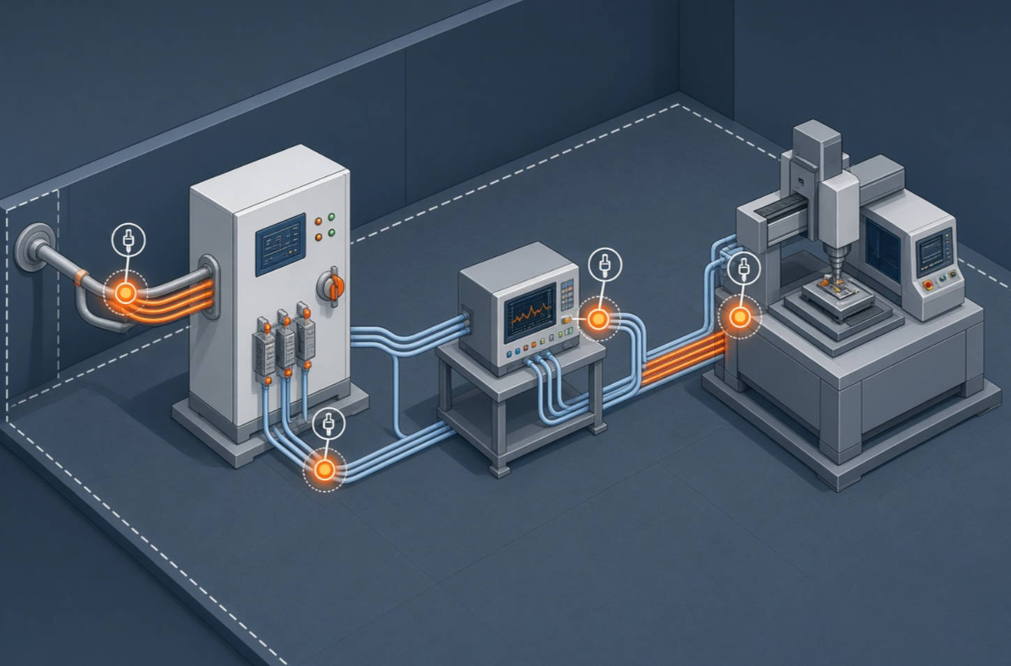
The most expensive mistake is often buying a device before identifying the component that trips. A practical investigation connects measurements to a repeatable failure sequence.
1. Define the failure. Record which machine stopped, its operating mode, the first alarm, and the time needed to recover production.
2. Locate the sensitive load. Trace its main supply, control transformer, DC power supplies, contactors, drives, and interlocks.
3. Measure at useful points. Compare the incoming service, the relevant distribution bus, and the sensitive equipment's input where safe and feasible.
4. Capture complete events. Record retained voltage, duration, affected phases, pre-event conditions, and available waveform data.
5. Correlate timestamps. Match power-quality records to PLC, drive, protection, and production logs.
6. Test the proposed remedy. Confirm that the vulnerable component remains operational under the relevant disturbance, using a qualified test plan.
For comparable measurements, specify the measurement method as well as the instrument. IEC 61000-4-30:2025 defines methods for power-quality parameters including voltage dips, interruptions, unbalance, and harmonics; its Class A and Class S methods serve different measurement purposes. Engineers should document the instrument class and configuration used in their study.
| Record for each event | Why it matters |
|---|---|
| Date, time, and operating mode | Connects the disturbance to a process step |
| Minimum retained voltage on each phase | Shows the severity and phase pattern |
| Duration | Helps compare the event with equipment tolerance |
| First device alarm or trip | Points toward the actual weak link |
| Production effect and recovery time | Supports a business case for mitigation |
There is no single "voltage sag solution" for every factory. Choose by failure mode: the event's depth and duration, the load that must remain energized, and the consequence of a trip.
| Option | Best fit | Key qualification |
|---|---|---|
| Control-circuit improvement | A relay, contactor, or power supply trips before the main process load | Preserve required safety and protection functions |
| Dedicated UPS | Critical controls need stored energy through sags or interruptions | Check transfer behavior, capacity, and every control/interlock connection |
| Dynamic voltage restorer (DVR) | A sensitive load needs its input voltage restored during qualifying sags | Verify the device's voltage, duration, load, and energy limits |
| Static transfer switch | A suitable independent alternate supply exists | Confirm source independence and transfer compatibility |
| Distribution or starting changes | Repeated local sags follow motor starts or plant operations | Model the system and verify performance after changes |
A DVR is installed in series with a sensitive load and injects a controlled voltage to compensate for a disturbance. Published research demonstrates its operation under modeled fault conditions, but a simulation result is not a performance guarantee for a particular site.
Protect the whole shutdown chain. In an EPRI-documented etcher investigation, an installed UPS did not prevent shutdown because an emergency-off interlock and vacuum-pump controls remained vulnerable. After engineers changed the protected control arrangement, testing showed improved ride-through for the circuits examined. The lesson is not to add a larger UPS by default; it is to map every component capable of stopping the process.
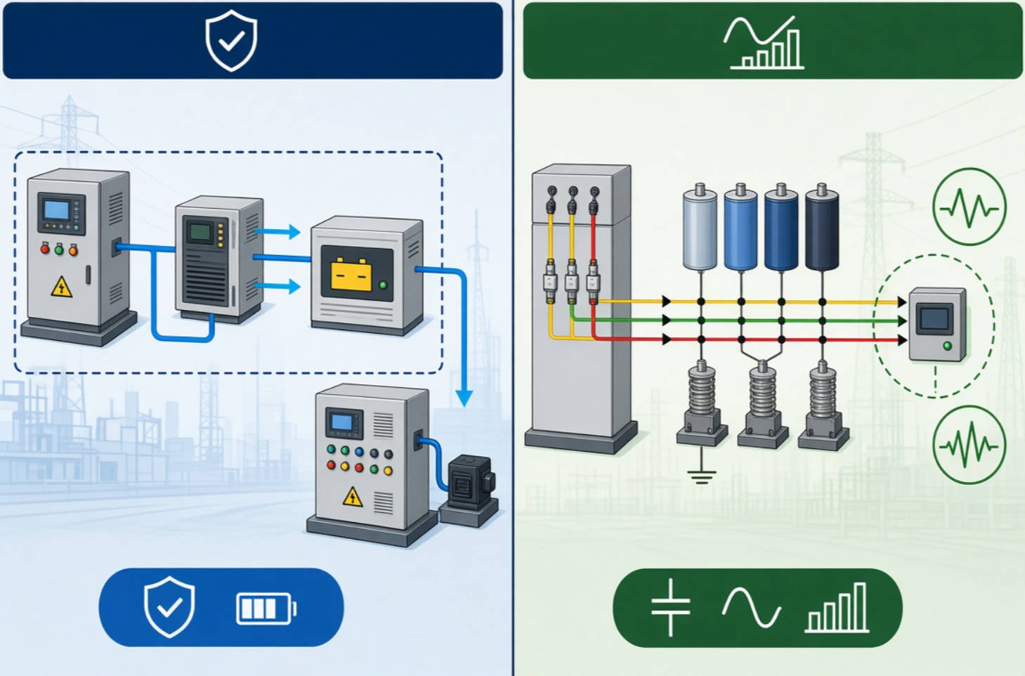
Equipment tolerance can be cheaper to improve than an entire facility supply. Ask machine suppliers for documented voltage-sag ride-through performance, including the operating conditions used during testing.
SEMI F47 offers one industry-specific example for semiconductor equipment: published guidance describes required tolerance at 50% retained voltage for 200 ms, 70% for 500 ms, and 80% for one second. Do not present these values as a requirement for every industrial machine. They are useful reference points when discussing immunity, while the applicable specification must match the equipment and procurement contract.
A plant with voltage sags may also have low power factor or harmonic distortion. These conditions deserve coordinated assessment, but they must not be treated as interchangeable.
Capacitor banks provide reactive power compensation. Reactors can be part of a compensation or harmonic-control design. These solutions may improve the electrical system's operating conditions, yet a conventional shunt capacitor bank is not a substitute for stored-energy ride-through or series voltage restoration when a sensitive load must survive a short, severe sag. The appropriate combination depends on measurements and system design.
Harmonic studies matter before adding capacitors to a system with nonlinear loads. IEEE 519-2022 addresses steady-state voltage and current waveform distortion at the point of common coupling; it does not serve as a voltage-sag immunity specification. Keep harmonic compliance, reactive compensation, and sag ride-through as separate acceptance criteria in the project brief.
For DINGNUO ELECTRIC CO., Ltd., this distinction shapes a responsible consultation. The company supplies capacitors, reactors, reactive power compensation, and harmonic-control products for industrial power-quality applications. A proposal for a site reporting shutdowns should first establish whether those products address a measured contributing condition—and whether separate sag-protection equipment or equipment-level changes are needed.
Before requesting quotations, provide each supplier with the same evidence. This makes technical proposals easier to compare and reduces the risk of purchasing a well-specified product for the wrong problem.
- Single-line diagram: Identify transformers, buses, major motors, compensation equipment, and sensitive loads.
- Event records: Provide phase-by-phase retained voltage, duration, waveform captures, and monitoring locations.
- Equipment data: Include rated voltage, load profile, control architecture, and known trip thresholds.
- Process priorities: Identify which loads must continue running and which can restart safely.
- Acceptance test: Define the disturbance conditions to be demonstrated and the required machine response.
For business evaluation, calculate the consequence of a documented event at your own site: lost output, scrap or rework, labor, restart time, and delivery impact. Avoid treating published loss figures from another industry as your plant's forecast. EPRI's semiconductor investigations show why weak-link testing and production context matter, but the return on mitigation must be calculated locally.
Voltage sag mitigation works best as a sequence: measure the event, identify the first failing component, select a targeted remedy, and verify ride-through. Capacitors and reactors can form an important part of a broader reactive power and harmonic-control strategy, but their role must be stated accurately alongside any dedicated sag-protection measures.
Need an engineering review? Send DINGNUO ELECTRIC CO., Ltd. your single-line diagram, recent power-quality event records, and list of affected equipment. Ask for an assessment of reactive power and harmonic conditions, plus a clear recommendation on whether separate voltage-sag mitigation is required.
No. During a sag, some voltage remains; an interruption involves a much more complete loss of supply. The distinction matters because equipment may tolerate one event but not the other.
Do not assume so. Capacitor banks are primarily selected for reactive power compensation. Whether a wider system design improves a specific voltage problem requires measurement and engineering analysis; short, severe sag ride-through generally calls for protecting the vulnerable load or its controls.
Measure voltage at points that can distinguish an incoming disturbance from a local one, then correlate each event with the first equipment alarm. Capture the voltage on the relevant phases, its minimum retained value, and its duration.
Start with the equipment whose trip causes the greatest disruption. Protecting a weak control circuit may be more appropriate than conditioning an entire plant, but the choice depends on the event records, process dependencies, and required operating continuity.
No. Its effectiveness depends on which loads and interlocks it actually supports. EPRI documented an etcher whose existing UPS did not prevent shutdown because vulnerable parts of the shutdown chain were outside effective protection.
Yes, as parts of one power-quality project—but give each a separate measured baseline, proposed remedy, and acceptance test. IEEE 519-2022 addresses steady-state harmonic distortion at the point of common coupling, not sag ride-through.
1. [Original article: "A Technical Investigation of Voltage Sag," (YT) Electric]. Starting page supplied for this rewrite; its full article text could not be retrieved reliably, so no specific claim is attributed to its unavailable body. [ytelect]
2. [Vima P. Mali, R. L. Chakrasali, and K. S. Aprameya, "A Technical Investigation of Voltage Sag," American Journal of Engineering Research, 2015; reproduced by Power Quality Blog]. Background on sag characteristics, causes, and mitigation. This is a related research paper, not a verified copy of the supplied website article. [powerquality]
3. [Ahmed M. Saeed et al., "Power Conditioning Using Dynamic Voltage Restorers Under Different Voltage Sag Types," Journal of Advanced Research, 2016]. Technical explanation and simulated assessment of DVR operation. [pmc.ncbi.nlm.nih]
4. [EPRI, Power Quality Perspectives in the Semiconductor Industry, Signature newsletter, 1997]. Equipment-sensitivity findings and documented weak-link investigations. [restservice.epri]
5. [International Electrotechnical Commission, IEC 61000-4-30:2025: Power Quality Measurement Methods]. Standard overview; the linked listing identifies a later corrected version. [webstore.iec]
6. [IEEE Standards Association, IEEE 519-2022: IEEE Standard for Harmonic Control in Electric Power Systems]. Scope of steady-state harmonic-control goals at the point of common coupling. [standards.ieee]
7. [Pacific Gas and Electric Company, "Voltage Sag Immunity Standards—SEMI F47 and F42," Power Quality Bulletin No. 3, July 2018]. Industry-specific ride-through values and equipment-immunity guidance. [pge]


