
Views: 287 Author: Dingnuo ELectric Publish Time: 2026-08-16 Origin: Site


Content Menu
● What Is Harmonic Resonance in a Power System?
● Series Resonance vs. Parallel ResonanceA Four-Step Harmonic Resonance Assessmen
● Why Capacitor Banks Can Amplify Harmonics
>> Example: Why a "Correct" kVAr Rating May Still Be Wrong
● How Active Harmonic Filters Prevent Resonance Problems
>> Key Functions of an Active Harmonic Filter
● Active Filters, Detuned Reactors, or Both?
● A Four-Step Harmonic Resonance Assessment
>> 1. Measure the Actual Electrical System
>> 2. Identify Dominant Harmonic Sources
>> 3. Run Harmonic and Resonance Studies
>> 4. Select and Verify the Solution
● Understanding IEEE 519 at the PCC
● Industry Applications for Harmonic Control Solutions
● When Should You Upgrade Your Solution?
● Work With a Power-Quality Engineering Partner
● FAQ
>> 1. Can capacitor banks cause harmonic resonance?
>> 2. What is the difference between THDi and TDD?
>> 3. Can an active harmonic filter replace a detuned reactor?
>> 4. Which harmonic orders are most dangerous for capacitor banks?
>> 5. How do I size an active harmonic filter?
>> 6. Why do capacitor-bank fuses keep failing?
>> 7. Does IEEE 519 apply to every electrical panel?
In industrial power systems, resonance and active harmonic filters must be evaluated together—especially where capacitor banks, variable-frequency drives (VFDs), rectifiers, welding equipment, UPS systems, or other nonlinear loads operate on the same network. A capacitor bank can improve power factor and reduce reactive-power costs, but an incorrectly designed solution may amplify harmonics, trigger capacitor failures, and compromise production continuity.
At DINGNUO ELECTRIC CO., Ltd., we help industrial and municipal customers address reactive power compensation, harmonic mitigation, and power-quality risks with capacitor, reactor, and filtering solutions engineered around real operating conditions—not generic equipment selection.
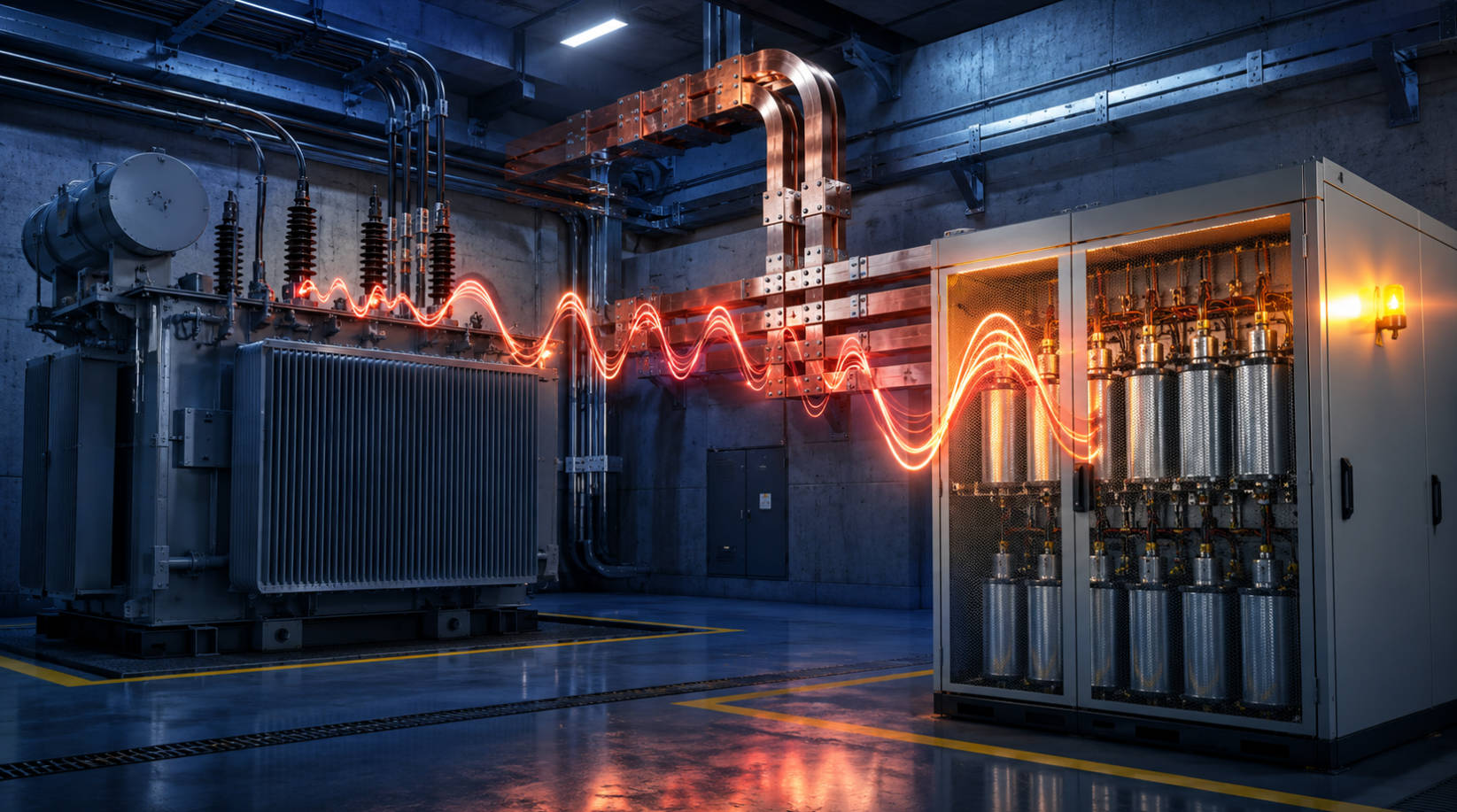
Electrical resonance occurs when the inductive reactance of the supply system and the capacitive reactance of capacitor banks become equal at a particular frequency. At or near this resonant frequency, voltage or current can increase sharply.
In a power distribution network, this is dangerous when the resonant frequency overlaps with a harmonic already produced by nonlinear loads.
Typical harmonic-producing loads include:
- Variable-frequency drives and soft starters
- DC drives and rectifiers
- Arc furnaces and welding machines
- Induction heating systems
- UPS systems and switch-mode power supplies
- LED drivers and electronic lighting ballasts
- High-capacity chargers and data-center loads
The key issue is not simply that harmonics exist. Modern industrial sites commonly have some harmonic distortion. The real risk emerges when the system configuration creates a path that amplifies a specific harmonic order, often the 5th, 7th, 11th, or 13th harmonic.
Expert perspective: In power-quality projects, capacitor-bank failures are often treated as a component-quality issue. In reality, repeated fuse operation, overheating, bulging capacitor cans, or reactor noise can be signs that the system was never fully assessed for harmonic resonance.
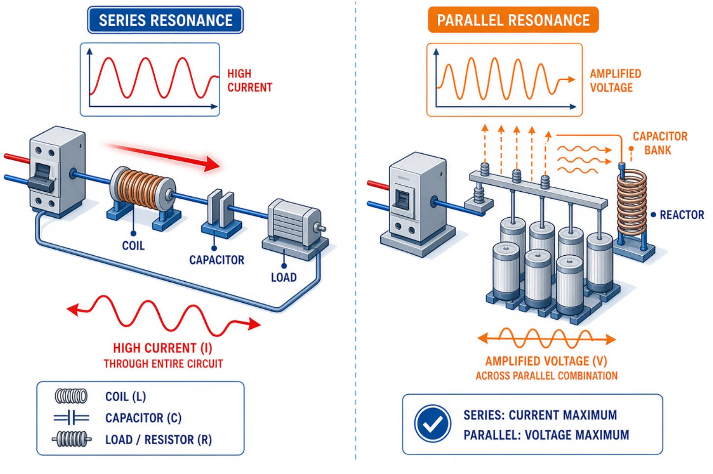
Both forms of resonance involve inductance and capacitance, but their operating behavior and consequences differ.
| Type | Circuit Condition | Main Effect | Typical Industrial Risk |
|---|---|---|---|
| Series resonance | Inductive and capacitive reactance cancel in series | Very low impedance and high current | Excessive current through branches or filter components |
| Parallel resonance | Inductive and capacitive branches interact in parallel | Very high impedance and voltage amplification | Harmonic-current amplification, capacitor overload, voltage distortion |
| Near resonance | Frequency is close to the resonant point | Significant amplification can still occur | Unstable operation during changing load or capacitor switching |
In commercial and industrial facilities, parallel resonance is particularly relevant to power factor correction capacitor banks. The system inductance may come from transformers, cables, generators, and upstream utility impedance, while the capacitance comes from installed capacitor steps.
When the resonant point is close to a characteristic harmonic frequency, the capacitor bank may attract harmonic current instead of only providing fundamental-frequency reactive power.
A conventional capacitor bank is highly effective for reactive power compensation under the right conditions. However, capacitance responds differently as frequency rises.
As frequency increases:
- Inductive reactance increases
- Capacitive reactance decreases
- The network impedance changes
- A resonant point can appear at a harmonic frequency
This means a capacitor bank should never be specified only by required kVAr. Engineers must also assess the network's short-circuit capacity, transformer impedance, existing harmonic spectrum, load profile, capacitor switching steps, and expected future expansion.
A widely used preliminary estimate for the parallel resonant harmonic order is:
hr≈sqrt{Ssc/Qc}
Where:
- hr = estimated resonant harmonic order
- Ssc = short-circuit capacity at the installation point
- Qc = installed capacitor-bank capacity
This calculation is a screening tool, not a replacement for a complete harmonic study. It helps identify whether a proposed capacitor step could move the resonant frequency toward a dominant harmonic order.
Assume a facility adds a 600 kVAr capacitor bank to correct poor power factor. The kVAr value may be appropriate from an energy-efficiency perspective. However, if the facility also operates VFD-driven pumps, compressors, or conveyor systems, the new capacitor capacity may shift the network resonant point toward the 5th or 7th harmonic.
The result may include:
- Capacitor fuse failures
- Reactor overheating
- High capacitor current
- Nuisance breaker trips
- Transformer temperature rise
- Protection relay misoperation
- Premature failure of sensitive automation equipment
The correct question is therefore not, "How many kVAr do we need?" It is: "What reactive-power compensation method will remain stable across our operating conditions?"
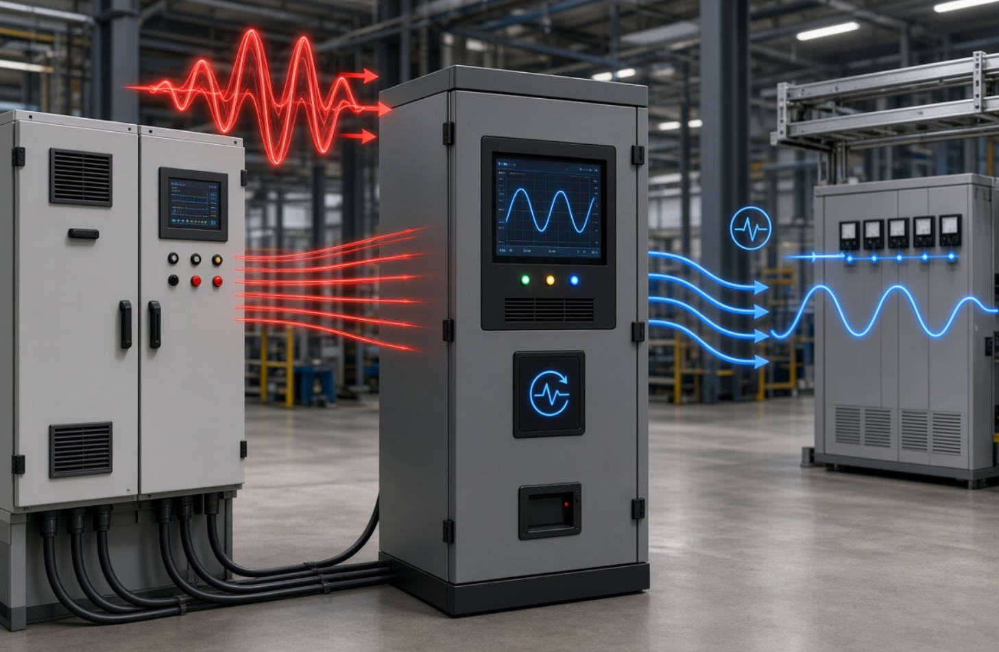
An active harmonic filter (AHF) continuously measures current distortion and injects compensating current with the opposite harmonic content. Rather than relying only on fixed passive components, it dynamically responds to changing load conditions.
This makes active harmonic filters valuable in facilities where nonlinear loads vary throughout the day.
- Detects harmonic currents in real time
- Injects compensating currents to reduce distortion
- Targets selected harmonic orders, such as the 5th, 7th, 11th, and 13th
- Helps improve current waveform quality
- Can support reactive-power compensation, depending on configuration
- Adapts to changing production loads
- Reduces harmonic current flowing through transformers, cables, and capacitor banks
An AHF does not eliminate the need for correct system design. If a capacitor bank is exposed to resonance risk, an active harmonic filter should be part of a coordinated solution that may also include detuned reactors, properly rated capacitors, and control-system adjustments.
There is no single harmonic-mitigation product suitable for every project. The right approach depends on the harmonic spectrum, load variation, voltage level, power-factor target, network impedance, and compliance requirement.
| Solution | Best Application | Main Strength | Important Design Consideration |
|---|---|---|---|
| Standard capacitor bank | Low-harmonic systems | Economical reactive power compensation | Must be assessed before installation where nonlinear loads exist |
| Detuned capacitor bank | Sites with moderate harmonic risk | Prevents capacitor-bank resonance and supplies kVAr | Reactor tuning must avoid dominant harmonic frequencies |
| Passive harmonic filter | Stable and known harmonic spectrum | Strong mitigation at targeted frequencies | Less flexible if loads change significantly |
| Active harmonic filter | Dynamic, mixed nonlinear loads | Real-time harmonic compensation | Must be sized using measured harmonic current and future load growth |
| Hybrid solution | Large industrial systems | Combines kVAr support with flexible harmonic mitigation | Requires coordinated engineering, tuning, and protection design |
For many factories, the most reliable architecture is a detuned capacitor bank plus active harmonic filtering. The detuned reactor helps keep the capacitor bank away from harmful resonance zones, while the AHF addresses variable harmonic currents created by production equipment.
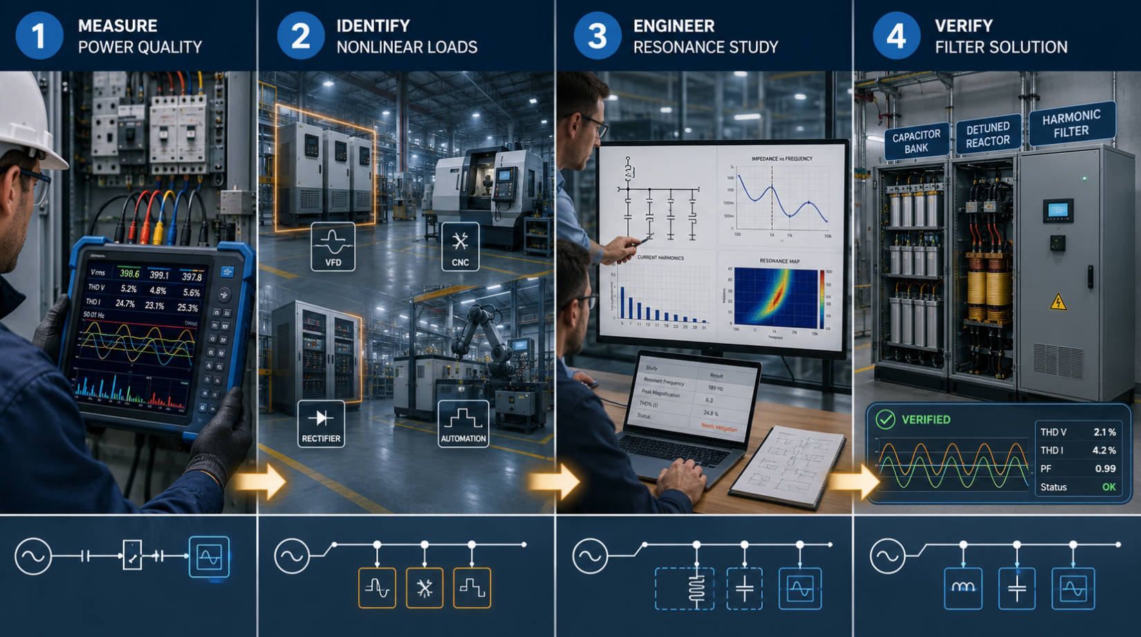
Before selecting capacitors, reactors, or filters, conduct a structured power-quality assessment.
Do not rely solely on nameplate information. Use a power-quality analyzer to collect data at the relevant bus or point of common coupling (PCC).
Measure:
- Voltage THD
- Current THD and total demand distortion (TDD)
- Individual harmonic orders
- Power factor and reactive power
- Load demand variation
- Capacitor switching events
- Transformer loading
- Short-circuit capacity where available
Important: A short measurement taken during low production may miss the actual problem. Monitoring should cover representative operating modes, including high-load shifts, equipment startup, and capacitor switching.
Map major nonlinear loads and determine when they operate. A factory may have a clean profile during one shift and severe distortion during another.
Focus on:
- Large VFD groups
- Rectifier-fed DC systems
- Induction furnaces
- Welding lines
- UPS systems
- High-speed automation lines
- Renewable-energy inverters
- Harmonic interaction between different workshops
Engineering analysis should test the network under multiple capacitor-bank switching conditions. This is essential for automatic power-factor correction cabinets, where each switched capacitor step can change the resonant frequency.
A complete review should assess:
- Existing and proposed capacitor capacity
- Individual capacitor switching stages
- Transformer impedance
- Cable and busbar impedance
- Generator operating modes
- Harmonic spectrum under peak production
- Likely resonance points
- Future expansion plans
After selecting a detuned reactor, capacitor bank, active harmonic filter, or hybrid configuration, verify performance through commissioning measurements.
A successful project should confirm:
- Capacitor current remains within allowable operating limits
- Resonant amplification is avoided
- Harmonic levels improve at the defined measurement point
- Power factor meets the facility target
- Protection devices coordinate correctly
- Filter capacity remains available for foreseeable load growth
IEEE 519 is widely used as a system-level reference for harmonic control. Its limits are applied at the point of common coupling (PCC)—the interface where a utility system may serve multiple customers—not automatically at every individual piece of equipment.
For voltage systems from above 1 kV through 69 kV, IEEE 519-2022 specifies a maximum total harmonic voltage distortion limit of 5% and a maximum individual voltage harmonic limit of 3% at the PCC. Current-distortion limits vary according to the ratio of short-circuit current to maximum demand load current, meaning weaker systems generally require stricter current-distortion control.
This distinction matters. A project should not select an active harmonic filter solely to chase a generic THDi number at one panel. It should begin with the desired electrical outcome: reliable equipment operation, protected capacitor banks, controlled voltage distortion, and compliance at the appropriate system boundary.
DINGNUO ELECTRIC supports power-quality solutions for demanding industrial and infrastructure environments, including:
- Metallurgy: Arc furnaces, rolling mills, and high-power drives can create severe and fluctuating harmonic loads.
- Petrochemical facilities: Continuous-process operations require stable electrical performance and strong equipment protection.
- Automotive manufacturing: Robotic welding, servo drives, testing equipment, and automated production lines increase nonlinear loading.
- Paper manufacturing: Large VFD-driven pumps, fans, and process motors often require coordinated reactive-power and harmonic control.
- Textile factories: Variable-speed motors and electronic controls can cause rapid load-profile changes.
- Building materials plants: Crushers, conveyors, kilns, and high-capacity motors demand robust power-factor correction solutions.
- Municipal infrastructure: Water treatment, rail, pumping stations, and public utility projects need dependable power quality under varying loads.
Consider a harmonic study or power-quality upgrade if you see any of the following warning signs:
- Capacitor-bank fuses repeatedly blow
- Capacitors overheat, swell, or fail prematurely
- Reactor temperature or noise increases abnormally
- Breakers trip without an obvious overload
- Transformer temperature rises unexpectedly
- VFDs, PLCs, or control systems behave erratically
- Voltage THD increases after capacitor-bank installation
- Power factor changes unpredictably
- A new production line introduces large drives, rectifiers, or automated equipment
Do not treat these symptoms as isolated equipment failures. They may indicate an underlying resonance condition that will continue until the system is measured and redesigned.
Reliable reactive power compensation starts with equipment, but it succeeds through system-level engineering. DINGNUO ELECTRIC CO., Ltd. provides capacitor and reactor products, harmonic-control solutions, and technical support for industrial and municipal power-quality projects.
Contact DINGNUO ELECTRIC today to discuss your electrical single-line diagram, transformer data, capacitor-bank capacity, harmonic measurements, and operating requirements. Our team can help evaluate whether a detuned capacitor bank, active harmonic filter, or hybrid solution is the best fit for your facility.
Yes. Capacitor banks can interact with the inductance of transformers, cables, generators, and the upstream network. If the resulting resonant frequency is near a harmonic generated by nonlinear loads, harmonic voltage and current may be amplified.
THDi uses the present fundamental current as its reference value. TDD uses the maximum demand current as the reference value. For system compliance evaluations, it is important to confirm which metric the specification requires, especially at the PCC.
Not always. An active harmonic filter can dynamically mitigate harmonic currents, but a detuned reactor is often necessary to prevent a capacitor bank from forming a harmful resonance condition. Many industrial projects benefit from using both technologies together.
The 5th and 7th harmonics are common concerns in facilities with six-pulse rectifiers and VFDs. However, the actual risk depends on the system's resonant frequency and measured harmonic spectrum. The 11th, 13th, and higher orders can also be problematic.
Active harmonic filter sizing should be based on measured harmonic current, the target reduction level, simultaneous load operation, planned future expansion, voltage level, installation location, and whether the device will also provide reactive-power compensation or load balancing.
Repeated fuse operation may result from capacitor inrush, incorrect protection coordination, excessive harmonic current, overvoltage, insufficient capacitor rating, or resonance. A power-quality measurement and resonance analysis should be completed before simply replacing the fuses or capacitors.
No. IEEE 519 is principally a system-level guideline focused on the PCC. Internal panel measurements remain useful for troubleshooting, equipment protection, and solution design, but they should not be confused with the formal system boundary used for compliance evaluation.
1. YT Electric. "Resonance and Active Harmonic Filters." Available at: [https://www.ytelect.com/blog/resonance-and-active-harmonic-filters_b221]
2. Carnovale, Daniel J., P.E. "Power Factor Correction and Harmonic Resonance: A Volatile Mix." Eaton / EC&M. Available at: [https://www.eaton.com/content/dam/eaton/products/low-voltage-power-distribution-controls-systems/power-factor-corrections/power-factor-correction-harmonic-resonance-white-paper-IA02607001E.PDF]
3. Eaton. "IEEE 519 Standard: What Do I Need to Know?" Available at: [https://www.eaton.com/us/en-us/products/controls-drives-automation-sensors/harmonics/harmonics-faq-video-library/ieee-519-standard-what-do-i-need-to-know.html]
4. Comsys. "Power Quality – IEEE 519-2022." Available at: [https://comsys.se/en-us/our-adf-technology/power-quality-ieee-519-2022/]
5. IEEE. "IEEE Std 519-2022: IEEE Recommended Practice and Requirements for Harmonic Control in Electric Power Systems." Available at: [https://standards.ieee.org/ieee/519/7372/]


