
Views: 211 Author: Dingnuo Electric Publish Time: 2026-10-20 Origin: Site


Content Menu
● What Is Neutral Current in a Three-Phase System?
● Main Reasons for High Neutral Current
>> Unequal Distribution of Single-Phase Loads
>> Triplen Harmonics from Nonlinear Loads
>> Mixed Loads and Changing Operating Conditions
>> Wiring Defects and Unintended Return Paths
● Why Neutral Current Can Exceed Phase Current
● How to Diagnose Excessive Neutral Current
>> 1. Map the Distribution System
>> 2. Measure All Phase Currents and Neutral Current
>> 3. Separate Fundamental and Harmonic Contributions
>> 4. Inspect Thermal and Connection Conditions
>> 5. Monitor Representative Operating Cycles
● Matching the Solution to the Cause
>> Balance Loads Using Measured Demand
>> Select Harmonic Mitigation for the Actual Current Path
>> Review Neutral Capacity and Protection
● Can Capacitors and Reactors Reduce Neutral Current?
● An Illustrative Industrial Troubleshooting Scenario
● Plan Your Neutral-Current Investigation with DINGNUO
>> 1. Is Some Neutral Current Normal?
>> 2. Why Is Neutral Current High When Phase Currents Are Balanced?
>> 3. Will a Capacitor Bank Eliminate Neutral Current?
>> 4. Do All Variable-Frequency Drives Produce Neutral Current?
>> 5. What Instrument Should Be Used to Measure Neutral Current?
>> 6. Should the Neutral Always Be Larger Than the Phase Conductors?
The main reasons for neutral current are unequal phase loading and harmonic currents from nonlinear electrical equipment. In a three-phase, four-wire system, these effects can occur separately or together. Understanding the difference is essential: balancing phase loads may reduce fundamental-frequency neutral current, but it will not necessarily eliminate harmonic current.
For industrial facilities, the practical concern is overheating. Excessive neutral current can stress cables, terminals, distribution panels, and transformers—even when phase-current readings appear acceptable.
At DINGNUO ELECTRIC CO., Ltd., our approach to reactive power compensation and harmonic control starts with identifying the electrical problem before selecting equipment. This guide explains what causes neutral current, how to investigate it, and where capacitors, reactors, and targeted mitigation measures fit.
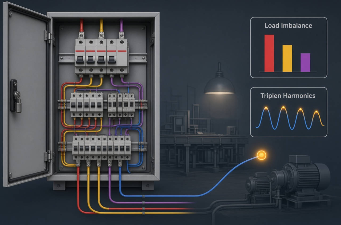
Neutral current is the current flowing through the neutral conductor, which provides a return path for phase-to-neutral loads.
With balanced sinusoidal phase currents separated by 120 electrical degrees, the three currents cancel at the neutral point. The theoretical neutral current is zero.
Real installations are rarely that simple. Lighting, control systems, computers, and other single-phase equipment draw different currents at different times. Electronic loads can also distort current waveforms.
The distinction matters:
- Fundamental-frequency imbalance produces a residual current in the neutral.
- Certain harmonic components can add in the neutral despite balanced phase loading.
- Wiring defects can create unintended current paths and complicate measurements.
Neutral current is therefore not automatically a fault. Its magnitude, frequency content, conductor capacity, and operating conditions determine whether intervention is necessary.
Uneven loading is a common cause of neutral current.
Consider a distribution board supplying office lighting on one phase, laboratory equipment on another, and intermittent workshop loads on the third. Their operating currents are unlikely to remain equal throughout the day.
The resulting fundamental neutral current is the vector sum of the phase currents—not their simple arithmetic sum.
Different phase power factors also affect this relationship. Equal current magnitudes do not guarantee cancellation if their phase-angle relationships differ from the balanced condition.
Load balancing should therefore consider operating schedules and electrical characteristics, rather than connected equipment ratings alone.
Nonlinear loads draw current in distorted waveforms rather than smooth sine waves. Examples include some LED drivers, computers, electronic power supplies, and single-phase rectifier equipment.
The third harmonic occurs at:
- 150 Hz in a 50 Hz system.
- 180 Hz in a 60 Hz system.
In a balanced system with similar phase-to-neutral nonlinear loads, third-harmonic currents can align in phase and add in the neutral. The ninth and fifteenth harmonics can behave similarly.
These odd multiples of the third harmonic are commonly called triplen harmonics.
Consequently, a panel can show similar phase-current readings while carrying substantial neutral current. Reallocating the same nonlinear loads among phases may improve fundamental balance without resolving this harmonic contribution.
Industrial sites often combine motors, drives, lighting, instrumentation, and office equipment.
These loads do not all affect the neutral in the same way. A typical three-phase, three-wire variable-frequency drive can generate supply harmonics, but it has no neutral connection through which to directly return phase-to-neutral load current.
By contrast, single-phase electronic loads connected between phase and neutral can directly contribute triplen neutral currents.
This distinction prevents a frequent diagnostic mistake: assuming that the largest harmonic-producing machine must also be the source of excessive neutral current.
Incorrect connections and unintended neutral-to-earth paths can alter current distribution.
They require investigation separately from ordinary load imbalance. A hot neutral terminal may indicate excessive current, a deteriorated connection, or both.
Unexpected neutral-to-earth voltage also needs context. It can reflect voltage drop along a loaded neutral, but the measurement alone does not identify the underlying cause.
Connection condition, earthing arrangement, load level, and measurement location must all be considered.
The explanation lies in how different frequency components combine.
Balanced fundamental currents cancel. Similar triplen components can reinforce one another.
Consider an illustrative system with these components on each phase:
| Current component | Value per phase | Result in the neutral |
|---|---|---|
| Balanced fundamental | 30 A | 0 A |
| In-phase third harmonic | 15 A | 45 A |
| Other components | Ignored | Ignored |
The total RMS current in each phase is:
Iphase=sqrt(302+152)≈33.5 A
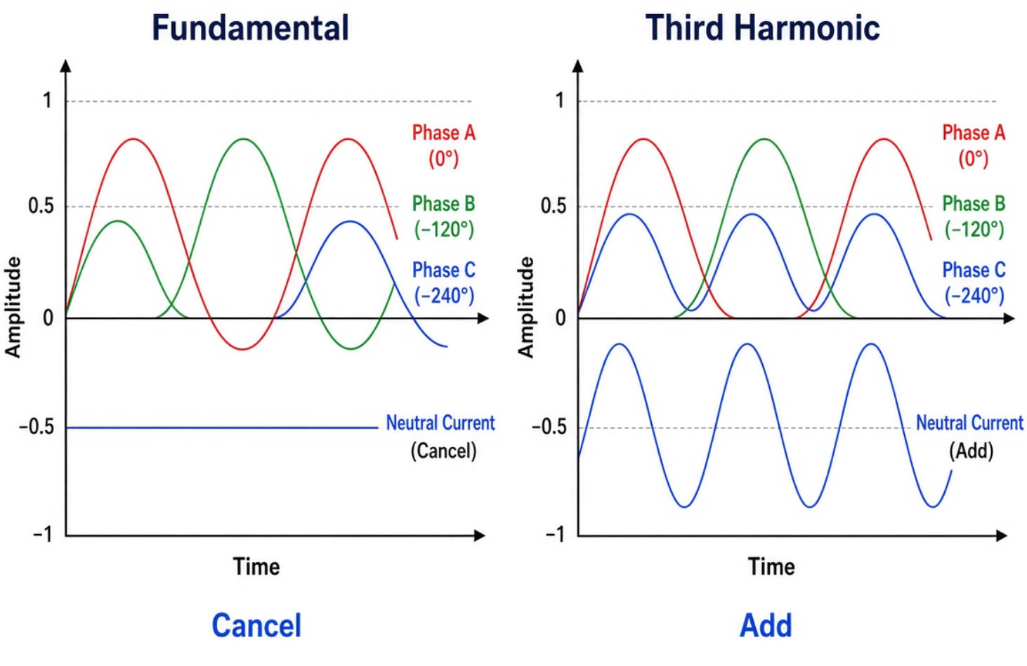
The neutral carries 45 A from the third harmonic alone.
Thus, the neutral current exceeds each phase current even though the phase loads are balanced.
This is a simplified engineering illustration, not a customer measurement. Real systems may contain multiple harmonic orders, unequal harmonic magnitudes, and different phase relationships.
The practical lesson is straightforward: phase-current balance does not prove that the neutral is adequately loaded.
Electrical testing should be performed by qualified personnel using appropriately rated instruments and site-specific safety procedures. Never disconnect an energized neutral as a diagnostic shortcut.
Start with the single-line diagram and identify:
- Transformer secondary configuration.
- Three-wire and four-wire feeders.
- Phase-to-neutral loads.
- Existing capacitor banks and reactors.
- Neutral conductor sizes and terminal ratings.
- Earthing and bonding arrangements.
This establishes where neutral current can physically flow.
Use a true-RMS instrument with suitable bandwidth and crest-factor capability.
For changing industrial loads, simultaneous measurements with a power quality analyzer are more informative than sequential clamp readings.
Record operating conditions alongside the electrical data. Otherwise, readings taken during different production states can create a misleading picture of imbalance.
Review the frequency spectrum rather than relying on total current alone.
Useful measurements include:
- Fundamental current on each phase.
- Neutral current spectrum.
- Third-, ninth-, and fifteenth-harmonic magnitudes.
- Current and voltage distortion.
- Phase-to-neutral voltages.
- True power factor and displacement power factor.
A large fundamental component suggests imbalance. Strong triplen components point toward nonlinear phase-to-neutral loads. Both may be present.
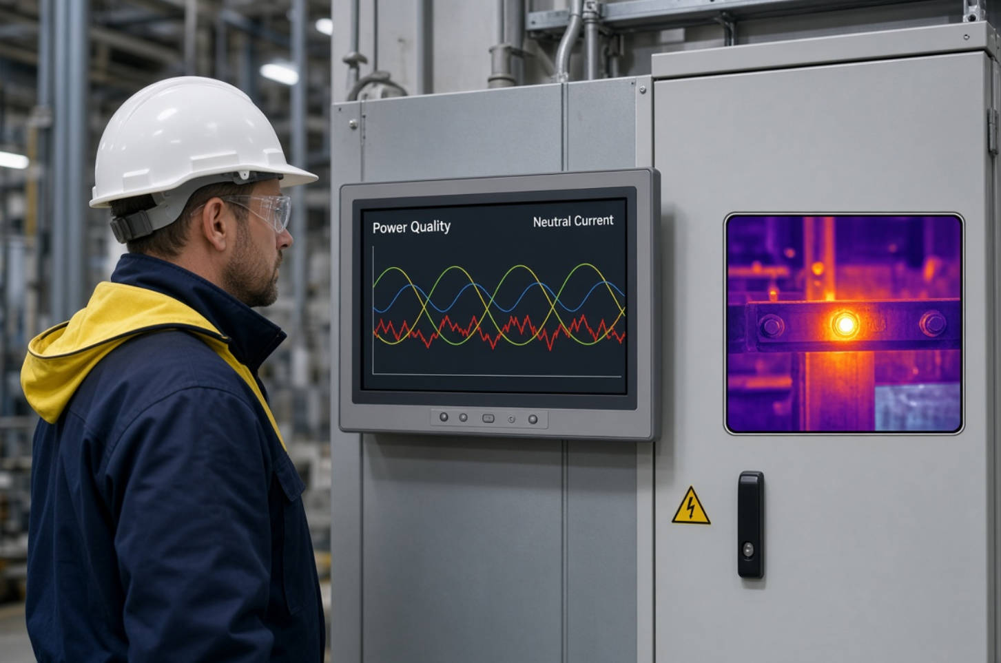
Assess neutral conductors, busbars, terminals, and transformer connections.
Thermal imaging can help locate abnormal heating, but interpret images alongside current measurements and equipment ratings.
A connection hotter than comparable terminals may indicate contact resistance. Uniform heating along a heavily loaded neutral suggests a different issue.
A single measurement can miss the problem.
Include production peaks, shift changes, lighting operation, and periods when compensation stages switch. Then correlate neutral current with the loads operating at those times.
This turns a collection of readings into an actionable diagnosis.
| Measured condition | Priority response | Important limitation |
|---|---|---|
| High fundamental neutral current | Redistribute single-phase loads | Does not inherently remove triplen harmonics |
| High triplen neutral current | Assess targeted harmonic mitigation | Equipment must support the required neutral-current function |
| Hot neutral connection | Inspect and repair the connection | Additional filtering cannot repair a defective joint |
| Insufficient neutral capacity | Review conductor, busbar, and protection design | Larger conductors do not remove harmonic sources |
| Capacitor stress in a distorted network | Study resonance and detuned compensation | Detuning is not automatically a neutral-current solution |
Redistribute circuits based on actual operating currents and schedules.
For example, balancing nameplate ratings may achieve little if one department operates continuously while another runs only intermittently.
Repeat measurements after redistribution. The improvement should appear in the fundamental neutral component, not merely in a more symmetrical panel schedule.
Where triplen harmonics dominate, evaluate mitigation designed for the system configuration.
A suitable four-wire active harmonic filter may provide neutral-current compensation. However, not every active filter has this capability.
Confirm the neutral-current rating, supported harmonic orders, control functions, and installation location. A three-wire device should not be assumed to solve a four-wire neutral-current problem.
Neutral sizing must account for expected current, installation conditions, and heating within the cable assembly.
Where harmonics load all four conductors, the additional heat can affect phase-conductor capacity too.
Avoid blanket rules such as always doubling the neutral. A qualified designer should apply the relevant installation requirements, equipment ratings, and measured harmonic conditions.
Power factor correction and neutral-current reduction address different electrical mechanisms.
Capacitors supply reactive power and can reduce the upstream reactive-current component associated with inductive loads. They do not inherently cancel third-harmonic current from phase-to-neutral electronic equipment.
Adding an ordinary capacitor bank to a harmonic-rich network can also introduce resonance or amplify existing harmonic currents.
Detuned reactors are connected in series with capacitor banks to control this interaction and protect the compensation assembly.
Their selection requires more than choosing a reactor percentage. Relevant inputs include:
- Network frequency and voltage.
- Dominant harmonic spectrum.
- Transformer and supply characteristics.
- Capacitor voltage rating.
- Compensation step sizes.
- Existing equipment and future load changes.
A detuned capacitor bank should not be presented as a universal neutral-current filter. Reactive compensation and neutral harmonic mitigation may require coordinated but separate measures.

Consider a textile facility where an auxiliary distribution panel develops a hot neutral connection after lighting and control equipment upgrades.
Phase RMS currents look reasonably balanced, so further circuit redistribution produces little improvement.
A power quality survey then identifies substantial third-harmonic current in the neutral.
An appropriate investigation would:
1. Identify which outgoing circuits contribute the triplen current.
2. Inspect the heated connection and associated conductors.
3. Verify neutral busbar and cable capacity.
4. Evaluate targeted mitigation.
5. Check existing compensation equipment for harmonic interaction.
6. Repeat electrical and thermal measurements after corrective work.
This scenario illustrates a diagnostic method; it is not a documented DINGNUO customer case.
The key insight is that similar phase readings can conceal very different waveform content.
DINGNUO ELECTRIC CO., Ltd. manufactures capacitors and reactors and provides reactive power compensation and harmonic control solutions for industrial and municipal applications.
Our project discussions should begin with the application requirements—not an assumed product selection.
For a technical enquiry, send your single-line diagram, system voltage and frequency, transformer rating, phase and neutral measurements, harmonic spectrum, and existing compensation details.
This information supports a clearer assessment of whether your facility needs load redistribution, compensation redesign, targeted harmonic control, or a combination of measures.
Yes. Unequal phase-to-neutral loads commonly produce neutral current. Whether it is acceptable depends on conductor capacity, connection condition, thermal performance, and applicable installation requirements.
Balanced RMS readings can conceal triplen harmonics. Their components may add in the neutral while balanced fundamental components cancel. A harmonic spectrum helps distinguish the two effects.
Not necessarily. Capacitor banks primarily compensate reactive power. They do not inherently remove neutral triplen currents, and harmonic-rich installations require assessment of resonance risks before adding capacitance.
No. Typical three-phase, three-wire drives have no neutral return connection. They may produce supply harmonics, but their impact differs from nonlinear equipment connected between phase and neutral.
Use a suitably rated true-RMS clamp meter for initial checks. A power quality analyzer is preferable when the investigation requires simultaneous phase measurements, harmonic spectra, and operating-cycle trends.
No universal sizing rule applies. The design must consider expected neutral current, harmonic heating, cable installation, terminal ratings, protection, and the applicable electrical requirements.
1. Shanghai Yingtong Electric Co., Ltd. "Reasons of Neutral Current." July 4, 2024. Original article used as the restructuring baseline. The retrieved page contained no customer reviews; none have been invented or attributed to DINGNUO. [ytelect]
2. Fluke Corporation. "Troubleshooting Power Harmonics: Basic Troubleshooting Using Multimeters and Current Clamps." Supports the explanations of nonlinear loads, triplen accumulation, true-RMS measurement, and diagnostic procedures. [fluke]
3. Schneider Electric. "A High 3rd Harmonic Current Can Cause a High Neutral Current." Technical FAQ supporting the distinction between load imbalance and additive third-harmonic currents. [se]
4. Schneider Electric, Electrical Installation Guide. "Sizing the Neutral Conductor." Updated August 5, 2026. Supports neutral-capacity assessment and cable-heating considerations in harmonic-rich four-wire installations. [electrical-installation]
5. M. R. Srinivas, Schneider Electric Blog. "Decoding Detuned Reactors: What and Why." October 7, 2015. Supports the discussion of capacitor resonance, series reactors, and coordinated capacitor–reactor selection. [blog.se]
6. Fluke Corporation. "How to Troubleshoot Harmonic Distortion in Data Centers." June 17, 2025. Supplementary guidance on harmonic investigation, thermal assessment, and mitigation approaches. [fluke]


