
Views: 254 Author: Dingnuo Electric Publish Time: 2026-09-24 Origin: Site


Content Menu
● What Is Power Factor and Why Does It Matter?
● Real-Time Power Factor Correction Explained
>> How a Real-Time PFC System Works
>> Contactor-Switched vs. Thyristor-Switched Capacitors
● What Is Active Power Factor Correction?
>> Where Active PFC Is Commonly Used
>> Why Active PFC Is Important for Harmonic Control
● Real-Time PFC vs. Active PFC: Key Differences
● Why Capacitor Banks Alone Are Not Always Enough
>> The Role of Detuned Reactors
● A Practical Selection Method for Industrial Facilities
>> Step 1: Measure the Existing Power System
>> Step 2: Identify the Dominant Problem
>> Step 3: Define the Performance Target
>> Step 4: Select an Engineered Solution
● Industry Applications and Engineering Priorities
>> Metallurgy and Heavy Manufacturing
>> Petrochemical and Process Plants
>> Paper, Textile, and Building-Materials Industries
● Expert Checklist Before Purchasing a PFC Solution
● Conclusion: Build a Power Quality Strategy, Not Just a Capacitor Bank
● FAQ
>> 1. What is the main difference between real-time PFC and Active PFC?
>> 2. Can a capacitor bank remove harmonics?
>> 3. When should a factory use a thyristor-switched capacitor bank?
>> 4. Does a power factor of 1.0 always provide the best result?
>> 5. Why are detuned reactors used with capacitor banks?
>> 6. Can Active PFC replace a plant-level reactive-power compensation system?
>> 7. What information is needed to size a power factor correction solution?
Industrial facilities need more than a "high power factor" on a monthly utility bill. They need a power-quality strategy that responds correctly to changing reactive-power demand, nonlinear loads, harmonic distortion, and the operating risks of capacitors, transformers, drives, and sensitive automation equipment.
For plant engineers, electrical contractors, and OEM decision-makers, the difference between real-time power factor correction and active power factor correction is essential. Although the terms are sometimes used interchangeably, they refer to different approaches, installation levels, and technical objectives. Selecting the wrong solution can lead to insufficient compensation, excessive switching, harmonic resonance, capacitor overheating, or avoidable utility charges.
DINGNUO ELECTRIC CO., Ltd. develops capacitor, reactor, reactive power compensation, and harmonic-control solutions for demanding industrial and municipal power systems. This guide explains how real-time compensation and Active PFC work, where each solution fits, and how to build a safer, more effective power-quality plan.
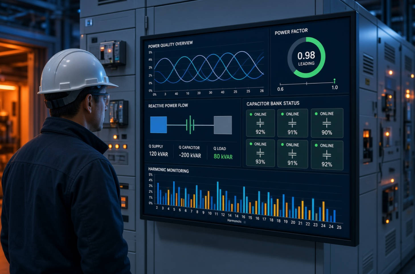
Power factor describes how effectively a facility converts electrical power from the grid into useful work. It is the relationship between real power, measured in kW, and apparent power, measured in kVA.
Power Factor=kW/kVA
A power factor close to 1.0 indicates that the electrical system uses supplied current efficiently. A lower power factor means the system requires more current to deliver the same useful output.
Inductive loads are the most common reason for low power factor in industrial facilities. These loads require magnetizing current to create magnetic fields, which produces reactive power measured in kVAr. Common examples include:
- Induction motors
- Transformers
- Welding machines
- Pumps and fans
- Compressors
- Magnetic lifting equipment
- Rolling-mill drives
- HVAC systems
- Conventional lighting ballasts
Reactive power does not directly produce useful mechanical work, but it still occupies capacity in transformers, cables, switchgear, and generators. The U.S. Department of Energy notes that reactive power places additional demand on both the source and distribution system, while power-factor correction capacitors can supply leading reactive current and reduce the current drawn from the upstream system.
For industrial users, a poor power factor can contribute to:
- Higher utility demand or reactive-power charges, depending on the local tariff
- Increased I2R losses in cables and transformers
- Reduced available capacity in existing distribution equipment
- Voltage drops during load changes
- More stress on generators, transformers, and switchgear
- Lower efficiency in heavily loaded power systems
The right correction method depends on how fast the load changes, whether harmonics are present, where the problem originates, and which power-quality targets apply at the facility's point of common coupling.
Real-time power factor correction is a system-level function. It describes a compensation system that continuously measures reactive-power demand and changes its output to follow variations in the electrical load.
Rather than adding a fixed capacitor bank that remains connected regardless of actual demand, a real-time PFC system uses an intelligent controller to monitor parameters such as:
- Power factor
- Reactive power in kVAr
- Voltage
- Current
- Harmonic distortion
- Load direction
- Switching status of capacitor steps
The controller then connects or disconnects capacitor stages, reactor-capacitor branches, or power-electronic compensation modules to maintain the selected target.
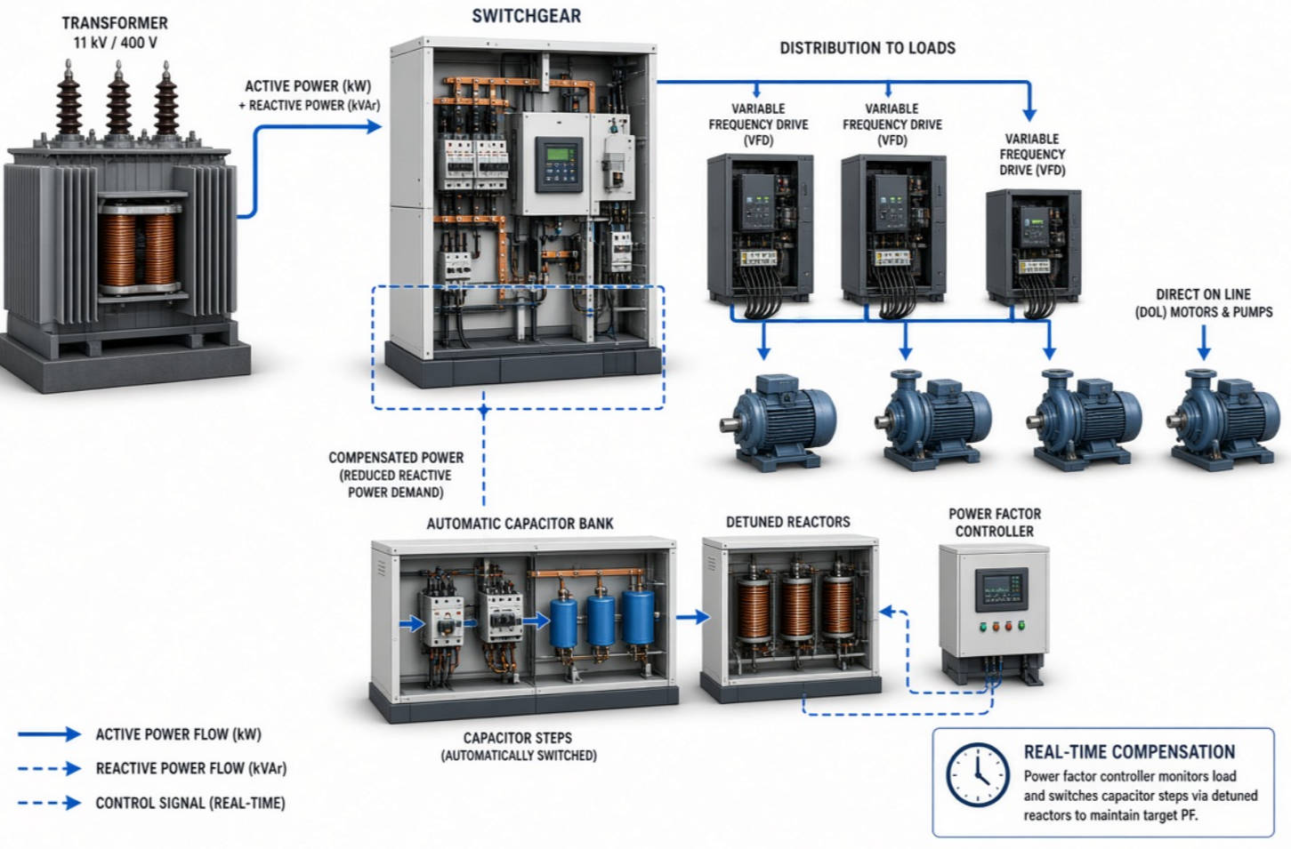
In a conventional automatic capacitor bank, the controller calculates whether the installation needs more or less capacitive reactive power. It then switches capacitor stages through contactors or thyristor switching devices.
A typical sequence looks like this:
1. A motor group, pump system, or production line starts operating.
2. The facility's inductive reactive-power demand increases.
3. The controller detects a lower power factor or increased kVAr demand.
4. The correction system connects one or more suitable capacitor stages.
5. As load demand falls, the controller removes unnecessary stages.
6. The system avoids overcompensation, which can create a leading power factor.
This approach is especially useful where load conditions change throughout the day, such as in manufacturing lines, pumping stations, workshops, textile operations, metallurgy plants, automotive factories, paper mills, and commercial facilities with large HVAC systems.
Not every "real-time" system has the same response speed. The switching technology determines whether the compensation system is suitable for slow, moderate, or highly dynamic loads.
| Solution type | Typical switching method | Best suited for | Key consideration |
|---|---|---|---|
| Contactor-switched capacitor bank | Mechanical contactors | Loads with relatively slow changes | Economical, but switching frequency must be managed |
| Thyristor-switched capacitor bank | Thyristors or semiconductor switches | Rapidly fluctuating loads | Fast response and reduced switching transients |
| Detuned capacitor bank | Capacitors combined with reactors | Networks with significant harmonic risk | Helps prevent harmonic amplification and resonance |
| SVG or STATCOM | IGBT-based converter | Very fast, continuously changing kVAr demand | Provides stepless dynamic reactive-power compensation |
| Hybrid compensation system | Capacitor bank plus SVG, AHF, or other active equipment | Plants with both base load and rapid fluctuations | Balances lifecycle cost and dynamic performance |
Contactor-switched systems remain practical for many industrial sites with gradual changes in load. However, frequent switching can shorten contactor life and may be unsuitable for applications with rapid load cycling.
Thyristor-switched capacitor systems are more appropriate for fast-changing loads, including welding equipment, presses, cranes, rolling mills, and rapidly changing motor loads. Their major advantage is fast switching at carefully controlled points on the voltage waveform, helping reduce switching transients.
Active Power Factor Correction, often called Active PFC, is a specific electronic circuit topology generally used inside an individual electrical or electronic device.
Instead of simply switching capacitor stages at the facility level, Active PFC uses high-speed power electronics—commonly a boost converter controlled by a dedicated control circuit—to shape the input current waveform. The objective is to make input current more sinusoidal and more closely aligned with the supply voltage.
In simple terms, an Active PFC circuit helps a device draw electricity in a cleaner and more controlled way.
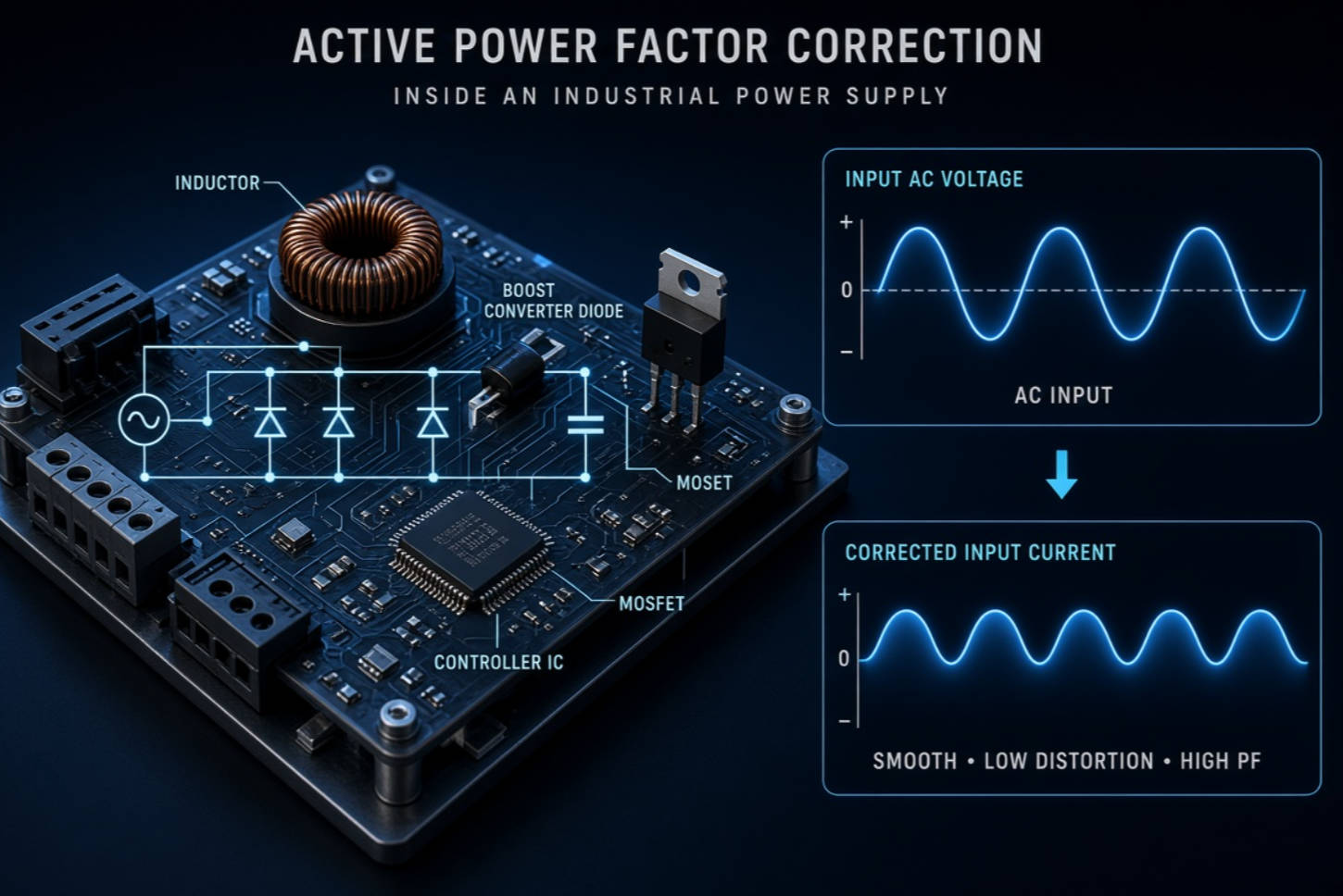
Active PFC is often integrated into equipment such as:
- Computer and server power supplies
- Telecom power systems
- UPS units
- LED drivers
- Battery chargers
- Consumer electronics
- Industrial switched-mode power supplies
- Data-center power equipment
- Variable-speed electronic equipment
The system usually includes:
- A PFC controller IC
- Inductor or boost choke
- MOSFET or IGBT switching device
- Diodes
- Capacitors
- Current-sensing and voltage-feedback circuits
- EMI filtering components
Unlike a plant-level capacitor bank, Active PFC works at the equipment input. It is designed to correct the current waveform produced by that device and support a more stable DC bus for downstream electronics.
Many electronic loads are nonlinear. Instead of drawing current evenly across the AC waveform, they can draw short pulses of current. This distorted current can produce harmonic currents, increase losses, heat transformers, overload neutral conductors, and affect the voltage quality seen by other equipment.
IEC 61000-3-2 addresses limits for harmonic current emissions from electrical and electronic equipment drawing up to 16 A per phase and connected to public low-voltage distribution systems.
Active PFC is one design approach that can help manufacturers reduce device-level harmonic current emissions and improve device input power factor. However, it should not be confused with a complete industrial power-quality system.
A facility can contain many devices with Active PFC and still experience poor overall power factor, harmonic distortion, resonance risk, or voltage-quality problems at the main distribution level.
The most important distinction is simple:
- Real-time power factor correction manages reactive power for an electrical system, feeder, panel, or facility.
- Active PFC is an electronic circuit inside an individual device that improves that device's input current waveform and power factor.
| Comparison point | Real-time power factor correction | Active power factor correction |
|---|---|---|
| Primary installation level | Facility, substation, switchboard, feeder, or distribution panel | Inside an individual electronic device |
| Main purpose | Match changing system-level reactive-power demand | Shape the input current of a specific device |
| Typical technologies | Capacitor banks, detuned reactors, thyristor switching, SVG, hybrid systems | Boost converters, inductors, MOSFETs, IGBTs, controller ICs |
| Compensation behavior | Step-based or continuously variable, depending on technology | Continuous high-frequency electronic control |
| Main beneficiaries | Industrial facilities, municipal projects, commercial buildings, process plants | Electronic power supplies and equipment manufacturers |
| Harmonic capability | Depends on the design; capacitors may require reactors or filters | Can reduce harmonic current generated by the individual device |
| Common risk if poorly designed | Resonance, overcompensation, capacitor stress, inappropriate switching | Higher circuit cost, thermal design requirements, component complexity |
This distinction matters during power-quality planning. A plant engineer should not expect Active PFC inside office equipment or LED drivers to solve reactive-power demand from hundreds of kilowatts of induction motors. Conversely, a central capacitor bank does not replace properly designed Active PFC in a high-performance switched-mode power supply.
A basic capacitor bank can be effective when the network has low harmonic content and reactive-power demand changes slowly. But modern industrial systems often contain variable-frequency drives, rectifiers, welding equipment, UPS systems, arc furnaces, renewable-energy converters, and other nonlinear loads.
These loads can generate harmonic currents. If capacitors are installed without a harmonic study, the combination of capacitor capacitance and system inductance may create resonance at or near a harmonic frequency. The consequences can include:
- Capacitor overheating
- Fuse operation
- High current in capacitor branches
- Excessive voltage distortion
- Reactor overheating
- Repeated equipment trips
- Shortened equipment life
- Unreliable compensation performance
IEEE 519-2022 establishes system-design goals for facilities containing linear and nonlinear loads and applies steady-state voltage and current distortion objectives at the user's point of common coupling. This is why harmonic compliance and correction performance should be evaluated at the system interface—not judged only by one drive, one filter, or one capacitor bank.
A detuned reactor is installed in series with a capacitor bank to shift the resonant frequency of the capacitor-reactor branch away from problematic harmonic frequencies.
For industrial users, detuned compensation can provide several benefits:
- Reduces the risk of harmonic resonance
- Limits harmonic current flowing into capacitors
- Improves capacitor reliability in nonlinear-load environments
- Supports stable reactive-power compensation
- Helps protect the distribution system from capacitor overload
The exact reactor selection should be based on measured harmonic content, system impedance, voltage level, capacitor rating, transformer capacity, and future expansion plans. There is no universal reactor percentage that is automatically correct for every site.
The best solution begins with measurements, not product selection. Before specifying a capacitor bank, SVG, active harmonic filter, or hybrid compensation system, evaluate the actual behavior of the network.
Use a qualified power-quality analyzer to collect representative data at the main incomer, relevant distribution boards, and major nonlinear-load feeders.
Measure:
- kW, kVAr, and kVA
- Average and minimum power factor
- Load profile over operating shifts
- Current THD and voltage THD
- Individual harmonic orders
- Transformer loading
- Voltage fluctuation
- Capacitor switching events
- Existing compensation performance
Measurements should cover normal production, peak production, low-load periods, and major process changes. A single short measurement may not capture the behavior of batch operations, variable-speed systems, or cyclical production lines.
Different symptoms require different solutions.
| Site condition | Recommended direction |
|---|---|
| Stable inductive load with low harmonic distortion | Automatic contactor-switched capacitor bank |
| Rapidly changing reactive-power demand | Thyristor-switched capacitor bank, SVG, or hybrid system |
| High harmonic current with capacitor overheating risk | Detuned reactor-capacitor bank and harmonic assessment |
| Strict distortion target at the PCC | Active harmonic filter, engineered passive filter, or hybrid solution |
| Large base reactive load plus sharp process fluctuations | Capacitor bank for base kVAr plus SVG for fast compensation |
| Sensitive automation equipment affected by voltage distortion | Full power-quality study, harmonic mitigation, and coordination review |
A sound engineering specification should define more than "power factor above 0.95." It should include:
- Target power factor range
- Required response time
- Expected kVAr compensation range
- Harmonic environment and allowable distortion
- Switching duty
- Voltage tolerance
- Temperature and installation conditions
- Expansion capacity
- Communication and monitoring requirements
- Protection requirements
- Applicable local utility, IEC, IEEE, or project standards
For many sites, maintaining a stable practical target—rather than constantly chasing a perfect 1.000 power factor—is more reliable and cost-effective. Overcompensation can create leading power factor and voltage-rise concerns, particularly during light-load conditions.
DINGNUO ELECTRIC supports reactive-power compensation and harmonic-control projects with solutions that can include:
- Low-voltage capacitor banks
- Intelligent power factor correction controllers
- Detuned reactor-capacitor systems
- Thyristor-switched capacitor banks
- Reactors for harmonic suppression and current limitation
- Static Var Generator solutions
- Active harmonic filtering solutions
- Hybrid reactive-power compensation systems
- Power-quality support for industrial and municipal applications
The final configuration should reflect the actual load profile, harmonic spectrum, electrical topology, operating objectives, and maintenance capability of the facility.
Metallurgical processes may include large motors, rolling equipment, welding systems, furnaces, cranes, and fluctuating mechanical loads. Reactive power can change quickly, while nonlinear converters may introduce significant harmonics.
A hybrid solution can be particularly effective: capacitor banks supply economical base reactive power, while SVG equipment responds quickly to transient or fluctuating kVAr demand. Where harmonics are substantial, active harmonic filtering or properly engineered passive filtering may also be necessary.
Petrochemical facilities often operate continuous process equipment with pumps, compressors, large motors, MCCs, and variable-frequency drives. Reliability is critical, and unplanned shutdowns can carry substantial operational consequences.
The engineering priority is not simply achieving a better power-factor reading. It is achieving a stable solution that coordinates with protection systems, avoids resonance, supports motor reliability, and performs across startup, normal production, and maintenance modes.
Automotive plants can combine robotic welding, conveyor systems, press shops, paint lines, compressed-air systems, HVAC loads, and high levels of automated control equipment.
Fast-changing welding loads may require high-speed compensation. Sensitive automation equipment also benefits from lower voltage distortion and a carefully controlled electrical environment. A plant-level survey should examine both reactive-power demand and harmonic behavior at critical panels.
These industries frequently use motor-intensive production equipment, pumps, fans, extruders, conveyors, dryers, and variable-speed drive systems. Their electrical load may change by product type, production stage, and shift schedule.
A modular compensation system can support staged expansion and make maintenance easier. The most reliable approach is one that matches the plant's real operating rhythm rather than its nameplate capacity alone.
Before approving a power-factor correction or harmonic-control project, ask these questions:
1. What is the measured kVAr demand during peak, normal, and low-load operation?
2. Does the site have VFDs, rectifiers, UPS systems, welding machines, or other nonlinear loads?
3. What are the current voltage and current harmonic levels at the PCC?
4. Is the proposed capacitor bank protected against harmonic resonance?
5. How quickly does the reactive-power demand change?
6. Is contactor switching fast enough for the actual process?
7. Could a capacitor bank create leading power factor during low-load operation?
8. Is a hybrid capacitor-plus-SVG solution more cost-effective than a fully active system?
9. Does the design allow future load expansion?
10. Are monitoring, alarms, protection, and maintenance access included in the specification?
A supplier that only asks for transformer capacity and target kVAr may not have enough information to provide a dependable long-term design. Professional solution selection requires electrical measurements, application understanding, and system-level coordination.
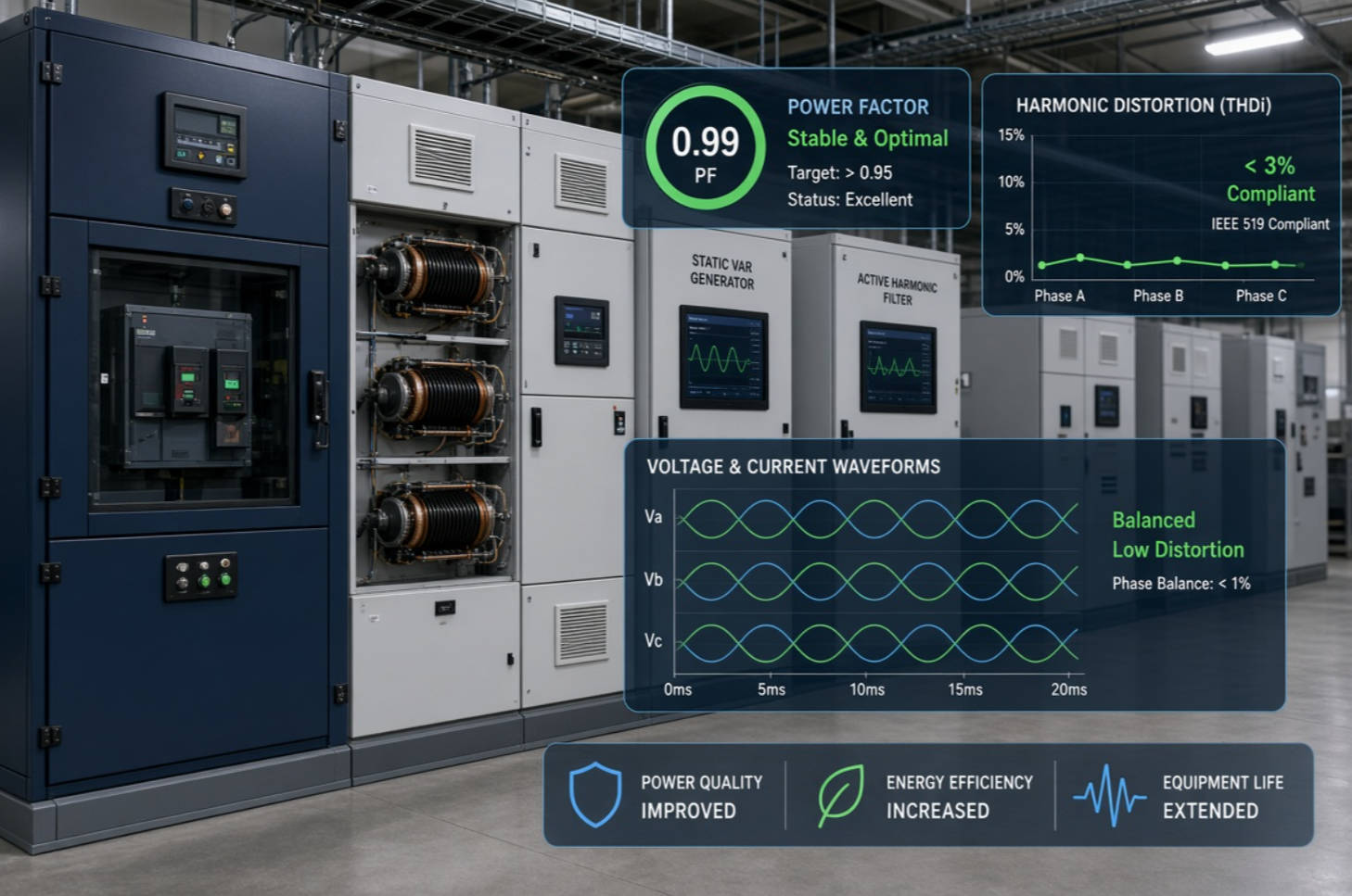
Real-time power factor correction and Active PFC are both valuable technologies, but they solve problems at different levels.
Active PFC improves the way an individual electronic device draws current. It supports cleaner input current, high device-level power factor, and reduced harmonic emissions from that equipment.
Real-time power factor correction manages the changing reactive-power needs of a wider electrical system. It can use contactor-switched capacitors, thyristor-switched capacitors, detuned capacitor banks, SVG equipment, or hybrid solutions to improve plant-level power factor and capacity utilization.
For facilities with motors, drives, nonlinear loads, and demanding production processes, the best result comes from a measurement-led, application-specific power-quality design. DINGNUO ELECTRIC can help evaluate your load profile, harmonic environment, compensation requirements, and project objectives to develop a reliable reactive-power compensation and harmonic-control solution.
Contact DINGNUO ELECTRIC today to discuss your power-quality assessment, capacitor bank, reactor, SVG, active harmonic filter, or customized industrial compensation project.
Real-time PFC is a system-level approach that adjusts reactive-power compensation for a panel, feeder, or entire facility. Active PFC is an electronic circuit inside an individual device that shapes its input current and improves its device-level power factor.
A standard capacitor bank is primarily designed to compensate reactive power, not remove harmonics. In a network with nonlinear loads, an improperly designed capacitor bank can amplify harmonic problems. Detuned reactors, active harmonic filters, or engineered passive filters may be needed.
A thyristor-switched capacitor bank is suitable when reactive-power demand changes quickly, such as in welding, presses, cranes, rolling mills, rapidly cycling motor loads, and dynamic industrial processes.
Not necessarily. A stable target power factor can be more practical than forcing the system to stay exactly at unity. Excessive correction can produce leading power factor, voltage rise, and unnecessary switching. The correct target depends on the utility tariff, site operating profile, and electrical design.
Detuned reactors reduce the risk that a capacitor bank will resonate with the electrical network at troublesome harmonic frequencies. They also help limit harmonic currents flowing into capacitors and improve reliability in installations with VFDs, rectifiers, UPS equipment, and other nonlinear loads.
No. Active PFC inside electronic equipment improves the input behavior of that particular device. It does not replace system-level compensation for large induction motors, transformers, industrial process loads, or fluctuating facility-wide reactive-power demand.
A proper design should use measured kW, kVAr, kVA, power factor, load profile, harmonic data, transformer capacity, voltage level, switching frequency, existing equipment, future expansion plans, and local utility or project requirements.
1. DINGNUO ELECTRIC / YT Electric. "Real Time Power Factor Correction and Active Power Factor Correction." [View the original article].
2. U.S. Department of Energy. "Continuous Energy Improvement in Motor Driven Systems." The guide explains reactive power, power-factor correction capacitors, and the effect of reactive current on electrical distribution systems. [Read the DOE guide]. [energy]
3. U.S. Department of Energy. "Improving Motor and Drive System Performance." The publication discusses power factor, system losses, utility penalties, and correction options for industrial motor systems. [Read the DOE publication]. [www1.eere.energy]
4. IEEE Standards Association. "IEEE 519-2022: IEEE Standard for Harmonic Control in Electric Power Systems." The standard establishes power-system design goals for voltage and current distortion at the user point of common coupling. [View the IEEE standard page]. [standards.ieee]
5. International Electrotechnical Commission. "IEC 61000-3-2:2018—Electromagnetic Compatibility: Limits for Harmonic Current Emissions." The standard concerns limits for harmonic currents emitted by equipment up to 16 A per phase connected to public low-voltage networks. [View the IEC standard page]. [webstore.iec]
6. IEC Webstore. "IEC 61000-3-2:2018 RLV." This official reference describes the scope of the standard and harmonic-current emission limits for applicable electrical and electronic equipment. [View the IEC Redline edition]. [webstore.iec]


