
Views: 273 Author: Dingnuo Electric Publish Time: 2026-10-03 Origin: Site


Content Menu
● Why Elevator Systems Create Harmonic Challenges
● Passive Harmonic Filter Explained
>> How a Passive Harmonic Filter Works
>> Main Benefits of Passive Harmonic Filters
>> Passive Harmonic Filter Limitations in Elevator Applications
● Detuned Harmonic Filter Explained
>> How a Detuned Harmonic Filter Works
>> Main Benefits of Detuned Harmonic Filters
>> Important Design Consideration: Capacitor Voltage
● Passive Harmonic Filter vs Detuned Harmonic Filter: Key Differences
● Which Solution Is Better for Elevator Systems?
● A Practical Selection Process for Elevator Projects
>> 1. Measure the Electrical Network
>> 2. Identify Harmonic Sources
>> 4. Select the Filter Architecture
>> 5. Verify Component Ratings
● Expert Insight: Avoid Treating Power Factor and Harmonics as the Same Problem
● Installation and Maintenance Recommendations
● Why Work With DINGNUO ELECTRIC CO., Ltd.
● FAQ
>> 1. What is the main difference between a passive harmonic filter and a detuned harmonic filter?
>> 2. Are detuned harmonic filters suitable for elevator variable frequency drives?
>> 3. Can a capacitor bank without reactors cause elevator electrical problems?
>> 4. Is a 7% detuned reactor always the best option for elevators?
>> 5. Does a detuned harmonic filter remove all harmonics?
>> 6. Should elevator harmonic filters be selected before or after power quality measurement?
>> 7. Can one harmonic solution serve elevators, HVAC drives, and UPS systems together?
Elevator systems increasingly rely on variable voltage variable frequency drives, regenerative drives, and sophisticated controllers. These non-linear loads can introduce harmonic currents into a building's electrical distribution system. Choosing between a passive harmonic filter and a detuned harmonic filter is therefore not simply a power factor correction decision. It directly affects elevator reliability, capacitor life, voltage quality, transformer loading, and maintenance risk.
For elevator projects, the best choice depends on the actual harmonic spectrum, the presence of capacitor banks, the electrical network strength, and the performance target at the point of common coupling. In most cases, a detuned harmonic filter is the safer solution for protecting capacitor banks in harmonic-rich elevator distribution systems. A properly engineered passive harmonic filter is more suitable when the project needs measurable attenuation of specific dominant harmonic orders.
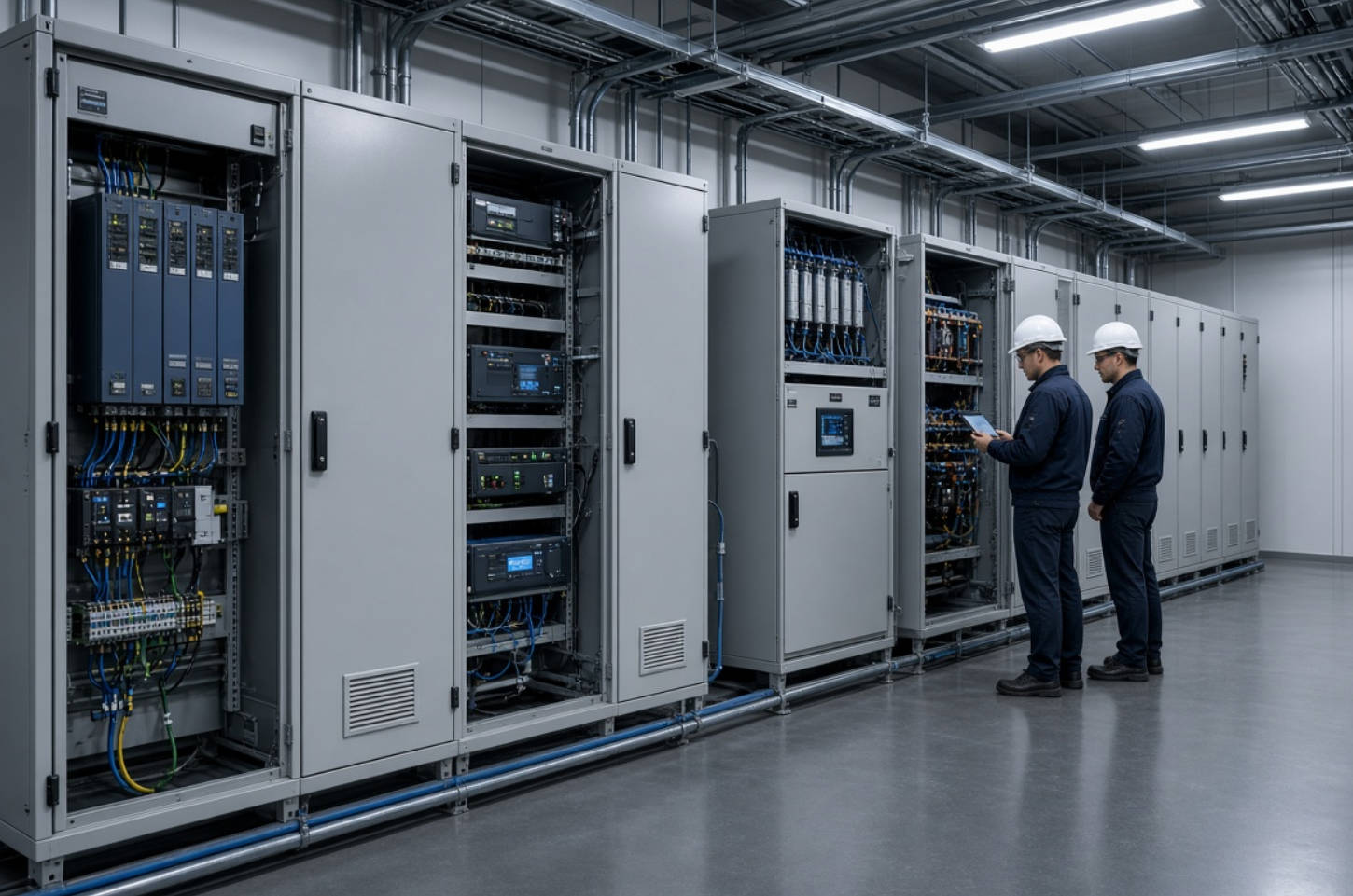
Modern elevators do not draw a perfectly sinusoidal current from the electrical supply.
Most traction elevators use variable frequency drives to regulate motor speed, acceleration, deceleration, and ride comfort. These drives convert AC power into DC and then back into controlled AC power for the motor. This conversion process creates harmonic currents.
Common harmonic-related symptoms in elevator electrical systems include:
- Capacitor overheating
- Repeated fuse operation
- Circuit breaker nuisance tripping
- Transformer temperature rise
- Audible noise in reactors or switchgear
- Higher losses in cables and busbars
- Unstable power factor correction
- Elevator drive alarms or control disturbances
- Reduced operating life of capacitors and contactors
An elevator load is also dynamic. Demand changes rapidly during acceleration, deceleration, peak traffic periods, and regenerative braking events. This makes a one-size-fits-all compensation design risky.
From an engineering perspective, the key question is not only, "How much reactive power is needed?" It is also, "Which harmonic frequencies are present, and how will the capacitor bank interact with the building network?"
A passive harmonic filter uses passive electrical components such as capacitors, reactors, and resistors to reduce harmonic currents or voltage distortion at selected frequencies.
In elevator systems, a passive filter is often installed near the elevator drive input, on the low-voltage busbar, or within a dedicated power quality panel. It creates a lower-impedance path for targeted harmonic currents, reducing the amount of harmonic current flowing back into the wider electrical network.
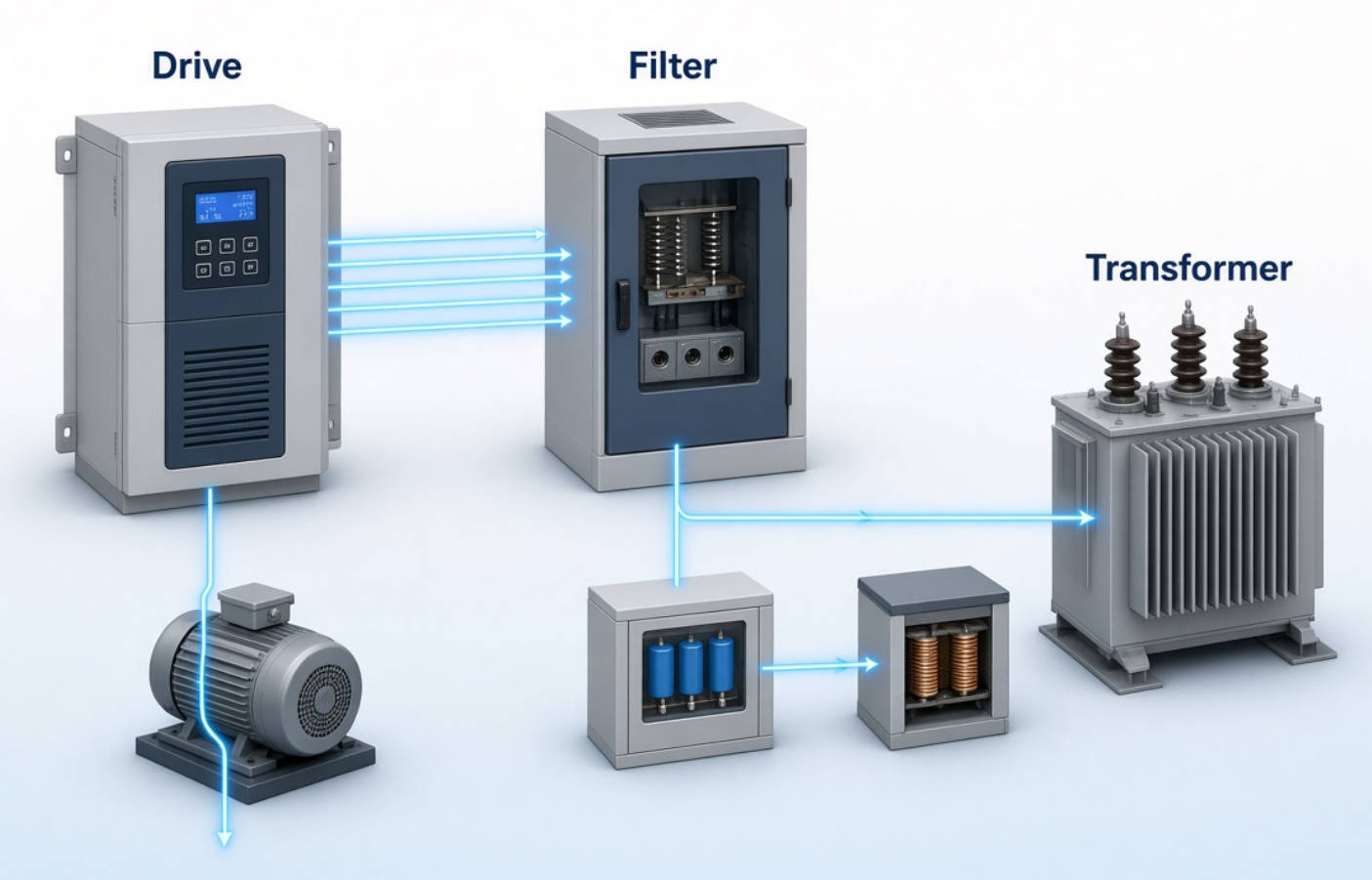
A typical passive harmonic filter uses an LC circuit:
- L represents inductance from the reactor.
- C represents capacitance from the capacitor.
- The circuit is designed around a target frequency or a range of frequencies.
The resonant frequency can be expressed as:
fr=1/2sqrt(LC)π
When correctly designed, the filter has low impedance near its tuning frequency. Harmonic current is attracted into the filter branch rather than circulating through transformers, cables, and upstream switchgear.
For example, a filter may be tuned to mitigate the 5th harmonic, which is frequently associated with six-pulse drive systems. Depending on the elevator drive design and system conditions, the 7th, 11th, and 13th harmonics may also matter.
A properly designed passive harmonic filter can provide several direct benefits:
- Reduces selected harmonic currents
- Lowers total harmonic distortion
- Improves voltage quality at the elevator distribution bus
- Reduces upstream transformer heating
- Reduces stress on cables, breakers, and busbars
- May provide reactive power compensation
- Works without active electronic control
- Offers a robust solution for stable, predictable load profiles
Passive filters are often attractive for projects requiring a cost-effective harmonic mitigation solution with no high-speed control electronics.
However, performance depends heavily on correct system analysis.
A passive filter is not automatically the best solution for every elevator project.
Its tuning must match the electrical environment. If the harmonic spectrum changes, the filter can become less effective. If the network impedance changes due to transformer upgrades, generator operation, or new non-linear loads, resonance conditions may also shift.
Potential limitations include:
- Risk of unintended resonance if engineering is incomplete
- Sensitivity to changes in network impedance
- Possible overload under unexpected harmonic conditions
- Need for accurate harmonic measurement before selection
- Limited flexibility when elevator load profiles vary significantly
- Physical space requirements for reactors and capacitors
For these reasons, passive harmonic filters should be specified only after a harmonic study, load analysis, and capacitor duty evaluation.
A detuned harmonic filter is a capacitor bank combined with series reactors. Its main purpose is not to absorb a specific harmonic order as aggressively as a tuned passive filter. Instead, it prevents the capacitor bank from creating or amplifying harmful resonance.
This distinction is critical.
In a building with elevators, capacitor banks are often installed to improve power factor. But capacitors naturally have low impedance at higher frequencies. When combined with transformer inductance and system impedance, they can form a resonant circuit.
If that resonant point falls near a dominant harmonic frequency, harmonic current may increase sharply. This can overheat capacitors, damage fuses, increase transformer losses, and create repeated electrical failures.
A detuned filter shifts the resonant frequency below the lowest important harmonic frequency. This helps prevent amplification rather than trying to capture all harmonic current.
The detuned reactor is connected in series with each capacitor step. The reactor adds inductive reactance to the circuit.
The design objective is to keep the system resonance frequency away from harmful harmonic frequencies.
| Detuning Factor | Typical Tuning Frequency at 50 Hz | Typical Application |
|---|---|---|
| 5.67% | ~210 Hz | Systems where 5th harmonic conditions require careful evaluation |
| 7% | ~190 Hz | Common choice for general industrial and commercial harmonic environments |
| 14% | ~135 Hz | Systems with notable 3rd harmonic influence or unbalanced conditions |
A 7% detuned reactor is often associated with a tuning frequency below the 5th harmonic in a 50 Hz system. Since the 5th harmonic occurs at 250 Hz, tuning around 189–190 Hz helps prevent resonance near that dominant frequency.
The correct selection must always consider the actual supply frequency, voltage, capacitor rating, harmonic voltage distortion, and load characteristics.
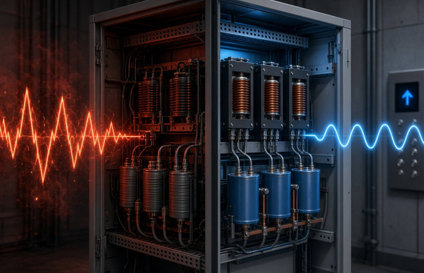
For many elevator installations, detuned capacitor banks provide a practical balance between power factor correction and harmonic risk control.
Key benefits include:
- Prevents harmonic resonance between capacitors and the network
- Protects capacitors from harmonic overcurrent
- Reduces capacitor thermal stress
- Supports more reliable reactive power compensation
- Reduces nuisance fuse operation and breaker tripping
- Helps protect transformers, cables, and switchgear
- Improves the stability of automatic capacitor bank switching
- Provides a durable solution for buildings with multiple elevator drives
Detuned filter systems are especially relevant where the electrical panel supplies elevator drives together with other non-linear loads, such as HVAC variable frequency drives, UPS systems, data equipment, EV chargers, or LED lighting systems.
A detuned reactor increases the voltage across the capacitor branch at the fundamental frequency. Therefore, capacitor voltage ratings must be selected carefully.
For example, a 400 V network may require capacitors with a higher voltage rating, such as 480 V or 525 V, depending on the detuning factor and system design.
Using ordinary capacitors without considering the reactor-induced voltage rise can shorten capacitor life and create avoidable failures.
Both technologies use capacitors and reactors. However, their engineering goals are different.
| Comparison Factor | Passive Harmonic Filter | Detuned Harmonic Filter |
|---|---|---|
| Primary purpose | Reduces targeted harmonic currents | Prevents resonance and protects capacitor banks |
| Filter behavior | Tuned toward one or more harmonic frequencies | Tuned below dominant harmonic frequencies |
| Harmonic reduction | Strong reduction at selected frequencies | Broad harmonic protection, less targeted attenuation |
| Power factor correction | May provide reactive power compensation | Combines reactive power compensation with anti-resonance protection |
| Typical elevator use | High harmonic levels requiring specific mitigation | Elevator buildings with capacitor banks and VFDs |
| Risk if poorly designed | Can create resonance or overload issues | Can underperform if detuning factor or capacitor rating is wrong |
| Sensitivity to system changes | Higher sensitivity | Usually more tolerant, but still needs engineering review |
| Maintenance needs | Periodic harmonic and tuning review | Capacitor, reactor, temperature, and switching inspection |
| Best selection basis | Measured harmonic spectrum + compliance target | Harmonic environment + capacitor-bank protection requirements |
The practical distinction is simple:
- Choose a passive harmonic filter when the objective is to reduce identified harmonic orders.
- Choose a detuned harmonic filter when the objective is to improve power factor while preventing capacitor resonance in a harmonic-rich elevator system.
There is no universal answer. The correct choice should follow electrical measurement and system modeling.
However, for many commercial buildings, hospitals, hotels, residential towers, office buildings, transport hubs, and mixed-use developments, a detuned harmonic filter is often the more conservative choice when capacitor banks are present.
This is because elevator drives and other modern building loads can produce variable harmonic conditions. A detuned system reduces the chance that power factor correction capacitors become the source of a larger harmonic problem.
A passive harmonic filter may be more appropriate when:
- Harmonic measurements show a persistent dominant harmonic order.
- The project has clear harmonic performance targets.
- Elevator drive loading is sufficiently predictable.
- The distribution network has been modeled.
- The filter is designed for expected future loads.
- Harmonic distortion must be reduced at a defined point in the network.
A detuned harmonic filter may be more appropriate when:
- A capacitor bank is required for reactive power compensation.
- Multiple elevator drives operate from a shared busbar.
- The building includes HVAC drives, UPS units, and other non-linear loads.
- Capacitor overheating or fuse failure has occurred.
- The existing capacitor bank has no series reactors.
- The electrical system may change over time.
A reliable solution begins with measurement, not assumption.
Record power quality data under realistic operating conditions. Measurements should include:
- Voltage THD
- Current THD
- Individual harmonic orders
- Power factor
- Capacitor current
- Transformer loading
- Voltage unbalance
- Peak elevator traffic conditions
- Generator operating conditions, if applicable
Measurements should cover periods of low, normal, and peak elevator demand.
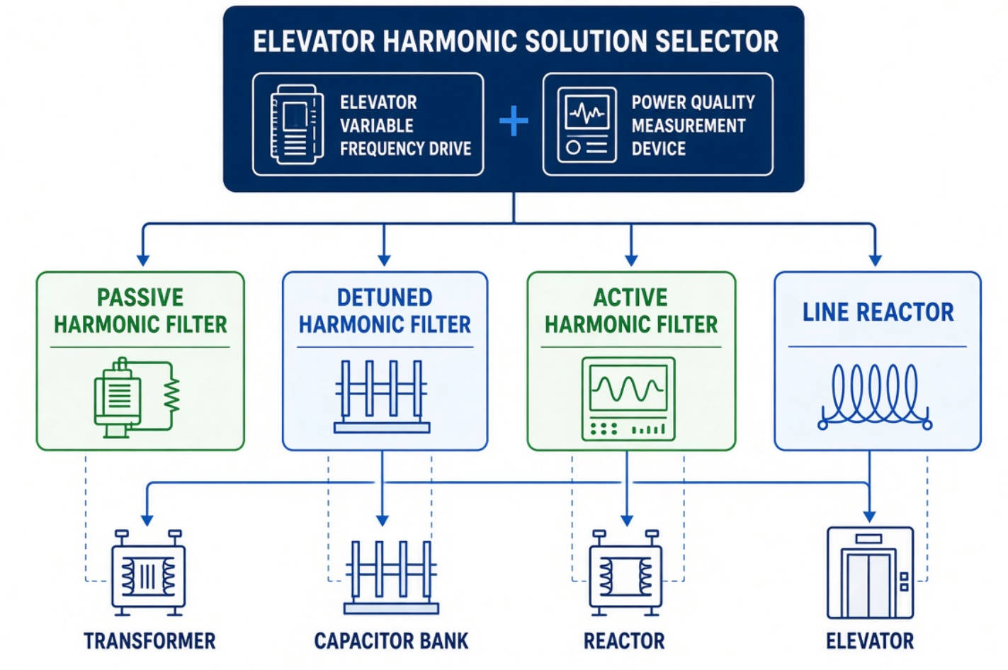
Do not analyze elevators in isolation.
Review all equipment connected to the same transformer or busbar, including:
- Elevator variable frequency drives
- Escalators and moving walkways
- HVAC drives
- Chillers
- Pumps
- UPS systems
- Data center loads
- EV charging stations
- Solar inverters
- LED lighting drivers
A capacitor bank may be located near elevators but can still be affected by harmonics from other loads.
Evaluate the relationship between:
- Transformer impedance
- Available short-circuit capacity
- Total capacitor kvar
- Existing reactor impedance
- Harmonic orders present
- Generator impedance, where standby generators are used
This step helps determine whether a capacitor bank could resonate near the 5th, 7th, or other relevant harmonic frequencies.
Use the measured data to select:
- Passive tuned filter
- Detuned capacitor bank
- Hybrid solution
- Active harmonic filter
- Line reactors or DC chokes at elevator drives
- A combined strategy
For high-rise buildings with several elevator groups, the best approach may involve detuned reactive power compensation at the main distribution level and harmonic mitigation closer to selected drive groups.
Component selection should include:
- Capacitor rated voltage
- Capacitor current capability
- Reactor thermal class
- Reactor linearity under harmonic current
- Fuse and breaker coordination
- Ventilation and enclosure temperature
- Switching method
- Installation altitude
- Cable sizing
- Electromagnetic compatibility requirements
Do not select capacitors by kvar alone. In elevator power systems, harmonic current capability and thermal performance are equally important.
One of the most common specification mistakes is to assume that adding capacitors will solve an elevator system's electrical efficiency problem.
Capacitors can improve displacement power factor. But they do not automatically reduce harmonic distortion. In fact, a capacitor bank installed without reactors can worsen harmonic conditions by creating resonance.
A sound elevator power quality strategy separates three questions:
1. Is reactive power compensation required?
2. Is harmonic reduction required?
3. Is resonance prevention required?
The answer may be different for each building.
For example, a building may need a detuned capacitor bank to safely correct power factor, while a separate passive or active harmonic filter is needed to reduce distortion created by a large elevator drive group.
This is why equipment selection should be based on measurement, engineering calculation, and future expansion plans.
A well-designed filter can still fail if installation and maintenance are neglected.
- Install reactors and capacitors in a ventilated enclosure.
- Maintain adequate clearance for heat dissipation.
- Keep power cables organized and correctly sized.
- Verify phase balance before commissioning.
- Confirm capacitor voltage rating matches the detuned design.
- Use temperature monitoring where high ambient temperature is expected.
- Coordinate protective devices with expected inrush and harmonic current.
- Test system behavior during elevator acceleration and regeneration.
- Inspect capacitors for bulging, leakage, and overheating.
- Measure capacitor current and branch voltage.
- Check reactor temperature and unusual noise.
- Inspect contactors, thyristor switches, fuses, and terminals.
- Repeat harmonic measurements after building expansion.
- Review performance after new elevators, HVAC drives, UPS systems, or EV chargers are added.
For critical facilities, periodic power quality monitoring provides early warning before capacitor damage or elevator-related electrical disturbances become severe.
DINGNUO ELECTRIC CO., Ltd. provides capacitors, reactors, reactive power compensation equipment, and harmonic control solutions for complex electrical environments.
For elevator systems, the engineering focus should be on more than supplying a standard capacitor bank. A reliable solution requires evaluation of the elevator drive characteristics, harmonic spectrum, transformer capacity, capacitor switching conditions, and installation environment.
DINGNUO ELECTRIC can support customers with:
- Reactive power compensation solutions
- Detuned reactor and capacitor bank configurations
- Passive harmonic filtering solutions
- Harmonic control equipment selection
- Customized product support for industrial and municipal projects
- Application-oriented technical consultation
- Solutions for power quality challenges across multiple sectors
For elevators in commercial buildings, industrial facilities, municipal infrastructure, and large-scale projects, a properly selected harmonic solution can improve reliability while reducing unnecessary stress on electrical assets.
For elevator systems with power factor correction needs and multiple non-linear loads, a detuned harmonic filter is often the preferred foundation because it protects capacitor banks from resonance and harmonic overload.
For projects with verified dominant harmonic orders and specific distortion-reduction objectives, a passive harmonic filter can deliver stronger targeted harmonic mitigation.
The right solution is not chosen by product name alone. It should be based on measured harmonic data, electrical network analysis, load diversity, and the required long-term reliability of the elevator power system.
Contact DINGNUO ELECTRIC CO., Ltd. for a technical assessment of your elevator distribution system, capacitor bank requirements, harmonic conditions, and customized power quality solution.
A passive harmonic filter is designed to reduce targeted harmonic currents, often at selected harmonic frequencies. A detuned harmonic filter combines capacitors and reactors to prevent resonance and protect capacitor banks in harmonic-rich systems.
Yes. Detuned harmonic filters are commonly suitable where elevator variable frequency drives operate with capacitor banks. They help reduce the risk of harmonic amplification and capacitor overload.
Yes. A capacitor bank without series reactors can resonate with transformer and network inductance. This may increase harmonic current, overheat capacitors, blow fuses, and create instability in the electrical distribution system.
No. A 7% reactor is common, but selection must be based on harmonic measurements, system voltage, frequency, dominant harmonic orders, capacitor rating, and the electrical network configuration.
No. Its primary purpose is to prevent resonance and reduce harmonic-related stress on capacitors and electrical equipment. If substantial harmonic reduction is required, a tuned passive filter, active harmonic filter, or hybrid solution may be necessary.
They should be selected after power quality measurement and engineering analysis. Measurements should include voltage distortion, current distortion, harmonic spectrum, transformer loading, and operating conditions during elevator peak demand.
Sometimes. A centralized solution may work if all loads share the same busbar and the electrical study supports it. In other cases, separate or coordinated solutions are better because different load groups may generate different harmonic patterns.
1. [TDK Electronics — Reactors for Power Factor Correction and Harmonic Filtering] — Technical information on resonance risks, detuned PFC systems, harmonic filter reactors, and common detuning factors. [tdk-electronics.tdk]
2. [Schneider Electric Blog — Decoding Detuned Reactors: What and Why] — Explanation of detuned reactors, capacitor protection, harmonic amplification, typical tuning frequencies, and practical benefits. [blog.se]
3. [Electrical Installation Guide — Possible Solutions for Power-System Harmonics] — Guidance on capacitor banks, detuned reactors, typical 5.7%, 7%, and 14% detuning factors, and harmonic-risk selection principles. [electrical-installation]
4. [IEC 61000-2-4:2024 — EMC Compatibility Levels for Industrial Power Systems] — Scope information for low-frequency conducted disturbances in industrial power systems up to 35 kV. [standards.iteh]
5. [Eaton — IEEE 519 Standard for Harmonics] — Overview of harmonic measurement and the importance of evaluating total harmonic distortion in power systems. [videos.eaton]


