
Views: 276 Author: Dingnuo Electric Publish Time: 2026-09-07 Origin: Site


Content Menu
● What Is the Difference Between High Voltage and Low Voltage Capacitors?
● High Voltage Capacitor vs Low Voltage Capacitor: Side-by-Side Comparison
● How Capacitors Improve Large Power Systems
● When High Voltage Capacitors Are the Better Choice
>> 1. Large Centralized Reactive Power Demand
>> 2. Medium-Voltage Motor Systems
>> 3. Substation-Level Voltage Support
>> 4. Better Fit for Large kVAR Requirements
● When Low Voltage Capacitors Are the Better Choice
>> 1. Local Compensation Near the Load
>> 2. Dynamic Industrial Load Profiles
>> 3. Modular Expansion and Lower Initial Investment
>> 4. Practical Retrofit Projects
● Harmonic Risk: The Most Important Factor Many Projects Miss
>> Detuned Reactors vs Harmonic Filters
● A Practical Selection Process for Large Power Systems
>> Step 1: Measure the Existing Electrical System
>> Step 2: Identify the Best Compensation Location
>> Step 3: Perform Harmonic and Resonance Assessment
>> Step 4: Select Switching Technology
>> Step 5: Define Protection and Safety Requirements
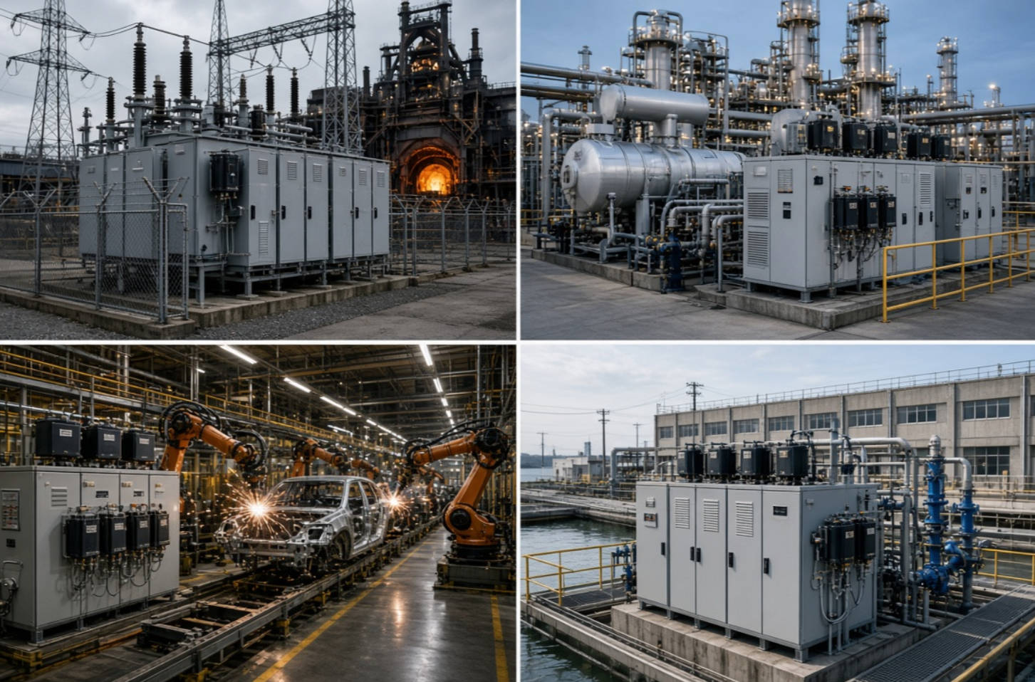
● Industry Application Examples
>> Metallurgy and Electric Furnaces
>> Petrochemical and Process Plants
>> Municipal Pumping and Water Treatment
● Which Solution Is Best for Your Facility?
● Conclusion: Design for Power Quality, Not Just Power Factor
● FAQ
>> 1. What is the main difference between a high voltage capacitor and a low voltage capacitor?
>> 2. Can a large factory use both high voltage and low voltage capacitor banks?
>> 3. Are low voltage capacitor banks suitable for factories with VFDs?
>> 4. Why do capacitors fail in industrial power systems?
>> 5. Should capacitor banks be installed at the transformer, main switchboard, or motor load?
>> 6. What is a detuned reactor in a capacitor bank?
>> 7. How often should industrial capacitor banks be inspected?
Choosing between a high voltage capacitor and a low voltage capacitor is not simply a matter of selecting a higher-rated component. For large power systems, the right solution depends on the electrical architecture, compensation location, harmonic profile, operating load pattern, protection philosophy, maintenance capability, and long-term power-quality targets.
At DINGNUO ELECTRIC CO., Ltd., we work with industrial customers that need reliable reactive power compensation and harmonic-control solutions in demanding sectors such as metallurgy, petrochemicals, automotive manufacturing, paper production, textile processing, construction materials, and municipal infrastructure. In these environments, a capacitor bank must do more than improve power factor. It must operate safely under voltage fluctuations, nonlinear loads, switching transients, elevated ambient temperatures, and harmonic currents.
This guide compares high voltage capacitors vs low voltage capacitors for large power systems from an engineering, procurement, and operating perspective. It also explains when reactors, detuned capacitor banks, harmonic filters, and automatic switching controls should be included in the final solution.
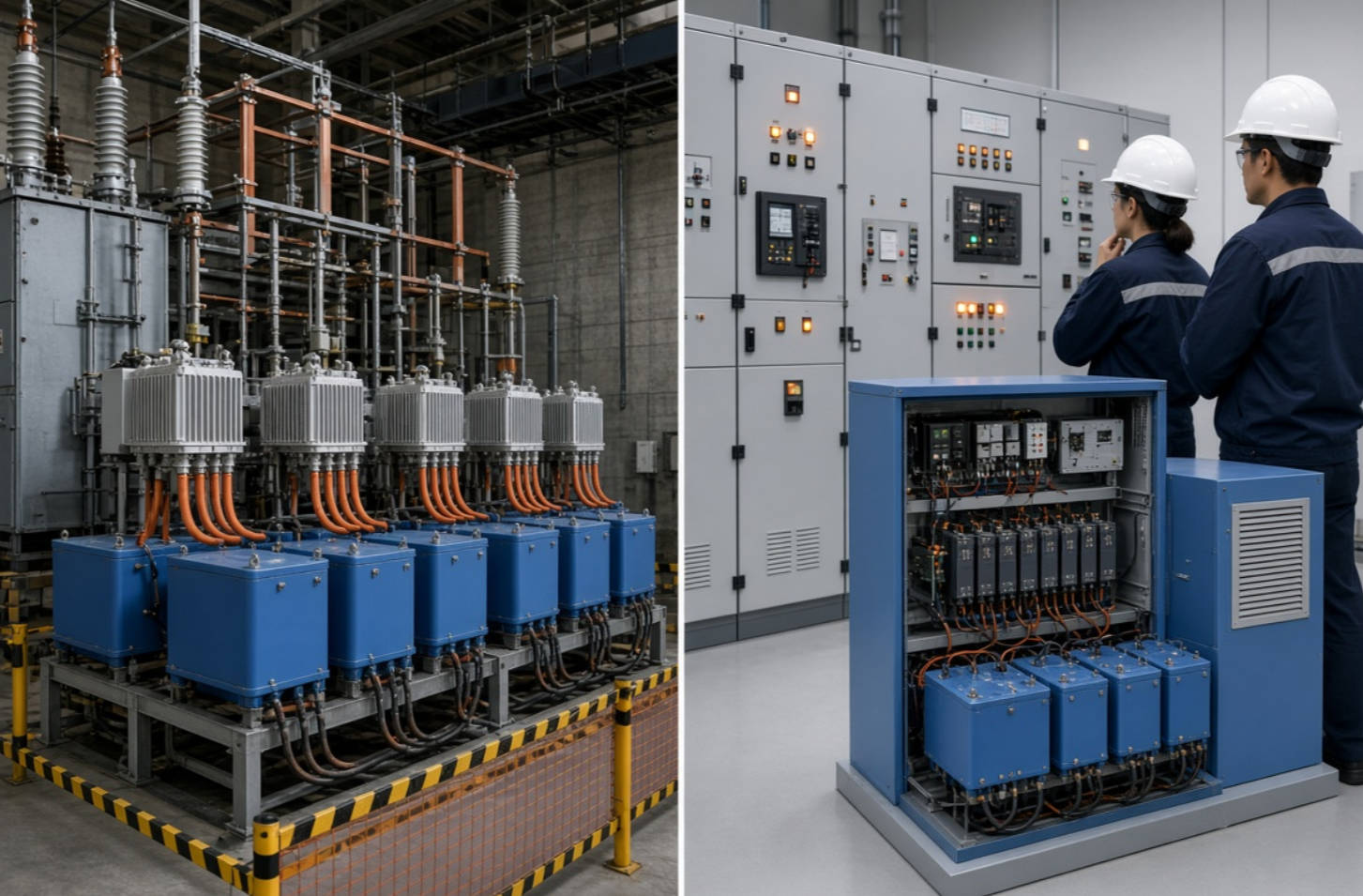
The basic difference is the voltage level at which the capacitor unit or capacitor bank is designed to operate.
A low voltage capacitor is generally applied in AC systems rated up to and including 1,000 V. Low voltage capacitor banks are commonly installed at 400 V, 415 V, 440 V, 480 V, 525 V, 600 V, or 690 V, depending on the site's electrical distribution system.
A high voltage capacitor is generally used in AC systems above 1,000 V. In practical industrial and utility applications, high voltage capacitor banks are often installed at medium-voltage levels such as 3.3 kV, 6 kV, 10 kV, 11 kV, 12 kV, 13.8 kV, 22 kV, 33 kV, or higher, depending on the system design.
The standards distinction is important. IEC 60831-1 applies to self-healing shunt power capacitors for AC systems up to and including 1,000 V, while IEC 60871-1 applies to shunt capacitors and capacitor banks for systems rated above 1,000 V.
However, voltage rating alone does not determine the best choice. A large facility may use both technologies at the same time:
- High voltage capacitor banks may provide bulk reactive power compensation at a substation or medium-voltage bus.
- Low voltage capacitor banks may compensate individual process areas, motor control centers, welding lines, pumps, compressors, or production machines.
- Detuned reactors and harmonic filters may be needed at either voltage level when nonlinear loads create harmonic risk.
| Comparison Factor | High Voltage Capacitor | Low Voltage Capacitor |
|---|---|---|
| Typical system voltage | Above 1,000 V | Up to and including 1,000 V |
| Common installation location | Utility substations, main substations, medium-voltage switchgear, large industrial incoming feeders | Main low-voltage switchboards, MCCs, distribution panels, individual production lines |
| Main compensation purpose | Bulk reactive power support, voltage regulation, feeder loss reduction, large-scale power factor improvement | Local power factor correction, reduced low-voltage current, demand charge reduction, equipment-level compensation |
| Typical switching equipment | Vacuum circuit breakers, contactors, fuses, disconnectors, protection relays, controlled switching devices | Capacitor contactors, thyristor switches, fuses, MCCBs, automatic power factor controllers |
| Physical size | Larger bank footprint and greater clearance requirements | Compact cabinet-based configurations are common |
| Installation complexity | Higher; requires medium-voltage insulation coordination, protection design, interlocking, grounding, and specialized commissioning | Lower than HV, but still requires correct cable sizing, ventilation, protection, discharge devices, and harmonic assessment |
| Harmonic sensitivity | Can be exposed to harmonic amplification and resonance; often requires detailed system studies | Highly vulnerable when installed on nonlinear load-rich buses without detuned reactors |
| Best for | Large centralized loads and medium-voltage distribution systems | Decentralized loads, dynamic production areas, and low-voltage distribution systems |
| Maintenance requirements | Requires trained medium-voltage personnel and stronger safety procedures | Easier access, but frequent inspection is still essential in harsh industrial environments |
| Capital cost | Usually higher per installed project due to MV equipment, protection, and civil requirements | Often lower entry cost, especially for modular automatic capacitor banks |
| Flexibility | Strong for large, stable reactive power demand | Strong for step-by-step automatic compensation near changing loads |
The key decision is not whether high voltage or low voltage is "better." The correct question is:
Where does the facility need reactive power, and what electrical risks exist at that point in the network?
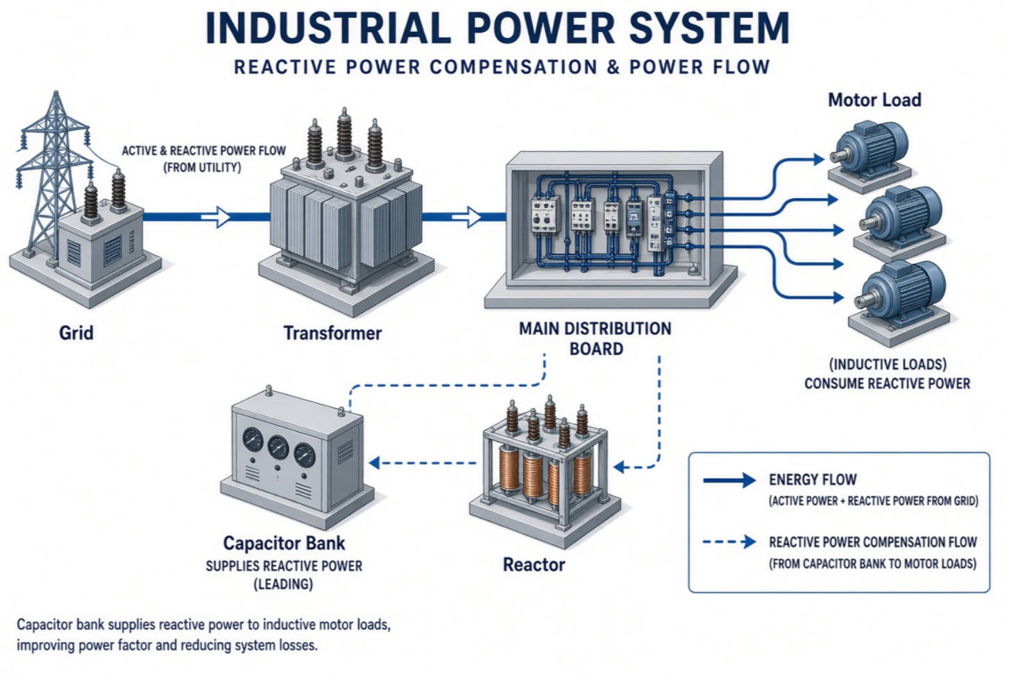
Capacitors supply leading reactive power, usually expressed in kilovolt-amperes reactive or kVAR. This offsets the lagging reactive power drawn by inductive equipment such as motors, transformers, welding equipment, furnaces, pumps, compressors, fans, conveyors, and inductive process loads.
A simplified compensation calculation is:
Qc=P(tanϕ1−tanϕ2)
Where:
- Qc is the required capacitor capacity in kVAR.
- P is the active load in kW.
- ϕ1 is the original power-factor angle.
- ϕ2 is the target power-factor angle.
For example, a plant with a 2,000 kW operating load may have a power factor of 0.78 and want to improve it to 0.95. The required capacitor capacity is approximately 1,170 kVAR. In reality, the final bank rating should not be selected from this formula alone. Engineers must also evaluate load variation, transformer impedance, harmonic distortion, voltage level, future expansion, switching frequency, and utility requirements.
Properly designed power factor correction can help a facility:
- Reduce unnecessary current in cables, transformers, and switchgear.
- Release capacity in existing electrical infrastructure.
- Improve voltage stability at heavily loaded buses.
- Reduce line losses associated with reactive current.
- Avoid power factor penalties where utilities apply them.
- Improve the electrical efficiency of large industrial systems.
- Support more stable operation of motor-driven processes.
Capacitor banks are widely used to help maintain bus voltage and provide power factor correction in distribution systems. IEEE notes that utilities use capacitor banks to support bus-voltage control and that IEEE Standard 18 sets withstand requirements for individual shunt power capacitors.
A high voltage capacitor bank is typically the better choice when a facility has substantial reactive power demand at the medium-voltage level or when compensation must support an entire substation, feeder, or large industrial site.
High voltage capacitor banks are suitable when major inductive loads are supplied from a medium-voltage bus. Typical examples include:
- Steel rolling mills and electric arc furnace facilities.
- Mining and mineral-processing plants.
- Large petrochemical complexes.
- Water-treatment and pumping stations.
- Cement plants and bulk material systems.
- Large paper mills.
- Utility distribution substations.
- Railway traction and municipal infrastructure projects.
In these applications, centralized MV compensation can reduce reactive-current flow through transformers and upstream feeders. This may improve available capacity and reduce the burden on the incoming electrical network.
Many large industrial motors operate directly at medium voltage. If a site has large MV motors driving compressors, crushers, mill drives, pumps, fans, or blowers, high voltage capacitor banks may be installed on the same MV bus or feeder.
This design can reduce reactive current upstream of the compensation point. It can also help support voltage during steady-state operation, provided that the switching strategy and transient behavior are properly engineered.
In systems with long feeders, weak-grid conditions, or significant voltage drop, a high voltage capacitor bank can provide local reactive power support. This may be particularly valuable in remote industrial facilities, municipal pumping projects, mines, and industrial parks with long distribution feeders.
However, capacitor switching must be carefully coordinated. A large bank switched onto a lightly loaded network can raise voltage excessively or create transient overvoltages. The bank may require staged switching, controlled switching, damping reactors, surge arresters, and protection relays.
High voltage capacitor systems can economically provide substantial kVAR capacity without forcing very high current through low-voltage conductors and switchgear.
For example, delivering 3,000 kVAR at 400 V requires a much larger current than delivering the same reactive power at 10 kV. Therefore, for large centralized compensation requirements, MV solutions often reduce conductor current and can simplify high-capacity distribution design.
Low voltage capacitor banks are often the most practical option when compensation is needed near changing industrial loads or within the low-voltage distribution system.
A low voltage capacitor bank can be installed close to the motors or process loads that consume reactive power. This reduces the reactive current flowing through the low-voltage distribution network.
For example, a textile factory may have separate groups of spinning machines, air compressors, HVAC systems, and motor-driven equipment. Installing an automatic low voltage capacitor bank near the relevant MCC or distribution panel can provide localized correction where it is needed.
This approach may improve:
- Cable loading.
- Local voltage performance.
- Transformer utilization.
- Equipment power factor.
- Electrical efficiency in individual production areas.
Many facilities do not have constant reactive power demand. Production lines start and stop. Welding machines cycle. Compressors load and unload. Pumps operate in stages. Extruders and variable-frequency drives change speed.
In these situations, an automatic power factor correction capacitor bank is often more effective than a fixed capacitor bank. The controller monitors reactive power or power factor and switches capacitor steps in or out as the load changes.
For fast-changing loads, conventional contactor switching may not be sufficient. Thyristor-switched capacitor banks can respond more quickly and reduce switching transients in applications with frequent load changes.
Low voltage capacitor banks are usually modular. A facility can begin with a measured compensation need and expand the system as production capacity increases.
This flexibility is useful when:
- A new factory is being commissioned in phases.
- Future equipment capacity is uncertain.
- The load profile is expected to change.
- The budget favors staged investment.
- Different workshops have different power-quality conditions.
In existing industrial facilities, installing a low voltage automatic capacitor bank may be easier than modifying medium-voltage switchgear. This is especially true when the major power factor issue is created by 400 V or 480 V motor loads.
Low voltage does not mean low risk. Capacitor banks installed on distorted networks can fail prematurely if harmonic currents are ignored. Low-voltage capacitor systems must be selected with the same engineering discipline as high-voltage systems.
In my experience with industrial power-quality projects, the most expensive mistake is often not selecting the wrong capacitor voltage. It is installing capacitor banks without understanding the facility's harmonic environment.
Nonlinear loads generate harmonic currents. Common sources include:
- Variable-frequency drives.
- Soft starters.
- Rectifiers.
- UPS systems.
- Welding machines.
- Induction furnaces.
- Arc furnaces.
- Battery chargers.
- LED lighting systems.
- Data-center power supplies.
- CNC machinery.
- Electroplating equipment.
Capacitors have lower impedance at higher frequencies. When capacitors are connected to a network containing harmonics, they can attract harmonic current. If the capacitor bank and system inductance create resonance near a dominant harmonic frequency, the result may be severe current amplification.
Possible consequences include:
- Capacitor overheating.
- Fuse operation.
- Bulging capacitor cases.
- Reactor overheating.
- Nuisance tripping.
- Excessive voltage distortion.
- Transformer overheating.
- Failure of sensitive electronics.
- Reduced capacitor service life.
- Production interruptions.
A practical warning sign is capacitor current that exceeds its rated current under normal system voltage. Eaton notes that a true-RMS current measurement more than roughly 5% above rated current can indicate harmonic-voltage distortion; it also notes that facilities with nonlinear load above 25% of main-transformer capacity will often require harmonic filtering with power factor correction.
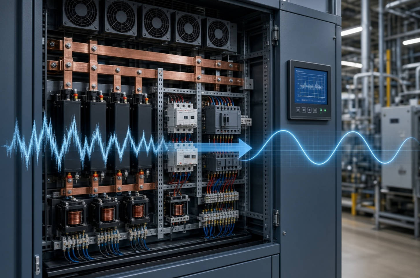
A detuned reactor is connected in series with a capacitor bank. Its primary purpose is to shift the system's resonant frequency below a problematic harmonic order, reducing the chance that the capacitor bank will amplify harmonic current.
A tuned harmonic filter combines capacitors and reactors to create a low-impedance path for a selected harmonic frequency, such as the fifth or seventh harmonic.
An active harmonic filter injects compensating current electronically and can address changing harmonic conditions across multiple harmonic orders.
| Solution | Main Purpose | Best Application |
|---|---|---|
| Standard capacitor bank | Power factor correction in a low-harmonic system | Stable, relatively clean electrical networks |
| Detuned capacitor bank | Power factor correction while avoiding resonance | Industrial sites with VFDs, rectifiers, welding, or moderate harmonic content |
| Tuned passive filter | Targeted reduction of specific harmonic frequencies | Large repetitive harmonic loads, furnace systems, rectifier-heavy plants |
| Active harmonic filter | Dynamic harmonic mitigation and reactive power support | Variable production loads, complex harmonic spectrum, sensitive equipment |
| Hybrid system | Combines passive and active technologies | Large plants requiring both high kVAR capacity and dynamic harmonic control |
For high voltage and low voltage applications alike, the correct answer begins with measurement. Do not assume that a capacitor bank can be safely installed based only on the monthly electricity bill or a spot power-factor reading.
The following engineering workflow helps reduce risk and improves project ROI.
Collect at least one representative load profile, preferably covering normal production, peak production, low-load operation, shift changes, and major equipment start-up periods.
Measure:
- Active power in kW.
- Reactive power in kVAR.
- Apparent power in kVA.
- True power factor.
- Displacement power factor.
- Voltage THD.
- Current THD.
- Individual harmonic orders.
- Transformer loading.
- Voltage variation.
- Capacitor switching events, if existing banks are installed.
A power-quality analyzer should be used rather than relying only on standard panel meters.
Ask where reactive power is consumed and where capacity constraints occur.
Choose high voltage capacitors when the main objective is centralized substation-level compensation, medium-voltage feeder support, or bulk kVAR supply.
Choose low voltage capacitors when the objective is localized correction near low-voltage loads, flexible step control, modular expansion, or retrofit convenience.
Use a combined HV and LV strategy when a site has both large centralized MV demand and multiple distributed LV production loads.
This step should include transformer impedance, cable impedance, existing capacitors, harmonic spectrum, VFD capacity, rectifier loads, and possible future expansion.
A harmonic study should determine whether the system needs:
- Standard capacitor banks.
- Detuned reactors.
- Tuned passive filters.
- Active harmonic filters.
- Hybrid compensation and filtering systems.
- Controlled capacitor switching.
Switching must match the load behavior.
- Contactor-switched banks are suitable for normal switching frequencies.
- Thyristor-switched capacitor banks are suitable for rapidly changing loads.
- Vacuum circuit breaker switching is common for high voltage capacitor banks.
- Controlled switching devices may be needed to reduce inrush current and switching transients in sensitive MV systems.
A reliable system includes more than capacitor units. It should include the correct protection, isolation, discharge, grounding, enclosure, ventilation, and monitoring design.
Important design elements may include:
- Capacitor fuses.
- Overcurrent protection.
- Unbalance protection for HV banks.
- Temperature monitoring.
- Overvoltage and undervoltage protection.
- Harmonic-current monitoring.
- Discharge resistors.
- Grounding switches.
- Surge arresters.
- Interlocks.
- Ventilation systems.
- Automatic controller alarms.
- Remote communication interfaces.
For capacitor safety, discharge requirements matter. Eaton's technical guide notes that capacitors rated at 600 V and below must discharge to below 50 V within one minute after de-energization, while capacitors rated above 600 V must discharge within five minutes.
Metallurgical facilities often combine large reactive-power demand with severe harmonic conditions. Arc furnaces, rolling mills, rectifiers, and large motor drives can create fast load changes and significant distortion.
A suitable solution may include:
- High voltage capacitor banks at the substation.
- Series reactors or tuned filters.
- Fast-switching compensation.
- Active harmonic filtering.
- Dynamic reactive-power control.
- Power-quality monitoring at the point of common coupling.
A standard low voltage capacitor cabinet without harmonic protection is rarely sufficient for this environment.
Petrochemical plants commonly operate large pumps, compressors, fans, and process motors. The power factor may be relatively stable in some areas but highly variable during process transitions.
A coordinated design may use:
- High voltage capacitor banks for bulk MV compensation.
- Low voltage automatic capacitor banks near MCCs.
- Detuned reactors where VFDs are widespread.
- Remote monitoring for maintenance planning.
- Segmented capacitor steps to match changing loads.
Automotive plants often combine robotic welding, painting lines, conveyors, compressors, machine tools, and variable-speed drives. The electrical environment can be dynamic and harmonic-rich.
A high-quality solution should prioritize:
- Fast response to changing load.
- Low-voltage detuned capacitor banks.
- Active harmonic filters near sensitive electronic loads.
- Harmonic measurement before and after installation.
- Scalable architecture for production-line expansion.
Water-treatment plants and pumping stations may have long feeders, large pumps, variable-frequency drives, and demanding reliability targets.
In these projects, high voltage capacitor banks can support the incoming distribution system, while low voltage harmonic-mitigated banks may serve individual pump stations or MCCs.
For most large facilities, the decision can be simplified as follows:
| If Your Primary Need Is… | Recommended Direction |
|---|---|
| Bulk reactive power compensation at 6 kV, 10 kV, or higher | High voltage capacitor bank |
| Power factor correction near 400 V, 480 V, or 690 V loads | Low voltage automatic capacitor bank |
| High nonlinear load from VFDs, welding, furnaces, or rectifiers | Detuned capacitors, harmonic filters, or active filters after system study |
| Rapidly changing load | Thyristor-switched capacitors or dynamic compensation |
| Both MV and LV reactive-power demand | Coordinated high voltage and low voltage compensation system |
| Existing capacitor failures, overheating, or nuisance trips | Immediate harmonic and resonance assessment before replacement |
| Expansion of industrial capacity | Modular, monitored, scalable capacitor and reactor solution |
The strongest strategy is often not "high voltage capacitor vs low voltage capacitor." It is a coordinated power quality architecture that places the right compensation technology at the right point in the electrical network.
High voltage capacitors and low voltage capacitors both play essential roles in large power systems. High voltage capacitor banks are highly effective for centralized reactive power support, medium-voltage bus compensation, and major industrial or utility-scale loads. Low voltage capacitor banks are ideal for local correction, modular installation, and automatic response to distributed factory loads.
But capacitor selection should never be separated from harmonic analysis. In modern industrial facilities, drives, rectifiers, welding systems, automation equipment, and electronic loads can turn a simple capacitor-bank project into a resonance risk if the design is incomplete.
DINGNUO ELECTRIC provides integrated solutions for reactive power compensation and harmonic control, including high voltage capacitors, low voltage capacitors, reactors, detuned capacitor banks, harmonic filtering equipment, automatic power factor correction systems, and customized power-quality solutions.
Contact DINGNUO ELECTRIC to request a system assessment, power-quality analysis, or customized high voltage and low voltage capacitor solution for your large power system.
The main difference is the rated system voltage. Low voltage capacitors are generally used in systems up to and including 1,000 V, while high voltage capacitors are used in systems above 1,000 V. The installation location, switching equipment, protection design, insulation requirements, and maintenance procedures also differ significantly.
Yes. Many large industrial facilities use high voltage capacitor banks at the medium-voltage substation for bulk compensation and low voltage capacitor banks near MCCs or production areas for local power factor correction. This combined approach can improve overall electrical efficiency and operating flexibility.
They can be, but standard capacitor banks may not be safe in VFD-heavy facilities. Variable-frequency drives generate harmonics that can overload capacitors or create resonance. A detuned reactor capacitor bank, passive harmonic filter, active harmonic filter, or hybrid solution may be required after a power-quality study.
Common causes include excessive harmonic current, overvoltage, inadequate ventilation, frequent switching, insufficient discharge time, failed contactors, poor protection coordination, resonance, incorrect kVAR sizing, loose connections, and operation above the capacitor's temperature or current limits.
The best location depends on where reactive power is consumed and where the system needs capacity support. Main-switchboard installation is common for centralized correction. Motor or MCC-level installation is useful for local correction. Medium-voltage substation installation is suitable for bulk reactive compensation. A professional system study should determine the optimal location.
A detuned reactor is a series reactor installed with capacitor stages. It helps prevent the capacitor bank from resonating with the electrical system at dominant harmonic frequencies. Detuned reactors are commonly recommended in facilities with variable-frequency drives, welding equipment, rectifiers, UPS systems, and other nonlinear loads.
Inspection frequency depends on the operating environment and criticality of the system. A practical program often includes routine visual and thermal checks, periodic torque verification, capacitor-current measurement, harmonic monitoring, ventilation inspection, controller review, and annual preventive maintenance. Facilities with high temperatures, dust, vibration, or severe harmonics may require more frequent inspection.
1. International Electrotechnical Commission. "IEC 60831-1:2014: Shunt Power Capacitors of the Self-Healing Type for A.C. Systems Having a Rated Voltage Up to and Including 1,000 V." [IEC Webstore]. [webstore.iec]
2. International Electrotechnical Commission. "IEC 60871-1:2014: Shunt Capacitors for A.C. Power Systems Having a Rated Voltage Above 1,000 V." [IEC Webstore]. [webstore.iec]
3. International Electrotechnical Commission. "IEC 61921:2017: Power Capacitors—Low-Voltage Power Factor Correction Banks." [Standards Australia]. [standards.org]
4. Eaton. "Power Factor Correction: A Guide for the Plant Engineer." [Eaton Technical Guide]. [eaton]
5. Eaton. "Proper Application of Power Factor Capacitors and How to Calculate Their ROI." [Eaton Application Guide]. [eaton]
6. IEEE Power & Energy Society. "Capacitor Banks." [IEEE Technology Navigator]. [technav.ieee]
7. IEEE. "Guide for the Protection of Shunt Capacitor Banks." [IEEE Xplore]. [ieeexplore.ieee]
8. Schweitzer Engineering Laboratories. "Principles of Shunt Capacitor Bank Application and Protection." [SEL Technical Paper]. [selinc]


