
Views: 263 Author: Dingnuo Electric Publish Time: 2026-09-03 Origin: Site


Content Menu
● What Are Third and Triplen Harmonics?
● The Direct Answer for 3-Phase, 3-Wire Systems
● Where Can Third Harmonics Go?
>> In Delta-Connected Windings
>> In Wye Systems Without a Neutral
>> In Wye Systems With a Neutral
>> During Unbalanced Conditions
● Why Third Harmonics Matter to Industrial Plants
● The Capacitor-Bank Risk Often Missed
>> Use Detuned Reactors When Needed
● A Practical Diagnostic Workflow
>> Step 1: Identify the System Topology
>> Step 2: Map Harmonic-Producing Loads
>> Step 3: Measure at More Than One Location
>> Step 4: Check Resonance and Capacitor Stress
>> Step 5: Select the Right Mitigation Method
● Engineering Perspective: Avoid a "No Third Harmonic" Assumption
● DINGNUO ELECTRIC Power Quality Solutions
● Request a Power Quality Assessment
● FAQ
>> 1. Are there third harmonics in a balanced 3-phase, 3-wire system?
>> 2. Why do third harmonics cancel in line-to-line voltage?
>> 3. Can third harmonic circulate inside a delta transformer winding?
>> 4. Why are third harmonics dangerous in a 3-phase, 4-wire system?
>> 5. Can capacitor banks worsen harmonic problems?
>> 6. Does low voltage THD mean that the power system is safe?
>> 7. What is the difference between THD and TDD?
Yes—third-harmonic components can be generated in a three-phase, three-wire electrical system, but under ideal balanced conditions they do not appear in the external line currents or line-to-line voltages. Instead, they may circulate within delta windings, remain confined by transformer connections, or emerge when load balance, grounding, or measurement conditions change.
For industrial facilities, this distinction matters. A plant may appear to have no third-harmonic issue at the incomer while still experiencing capacitor overheating, transformer thermal stress, nuisance protection trips, resonance, or poor power-factor-correction performance. The correct question is not simply, "Is there third harmonic?" It is: where is it generated, where can it flow, and what equipment is exposed to it?
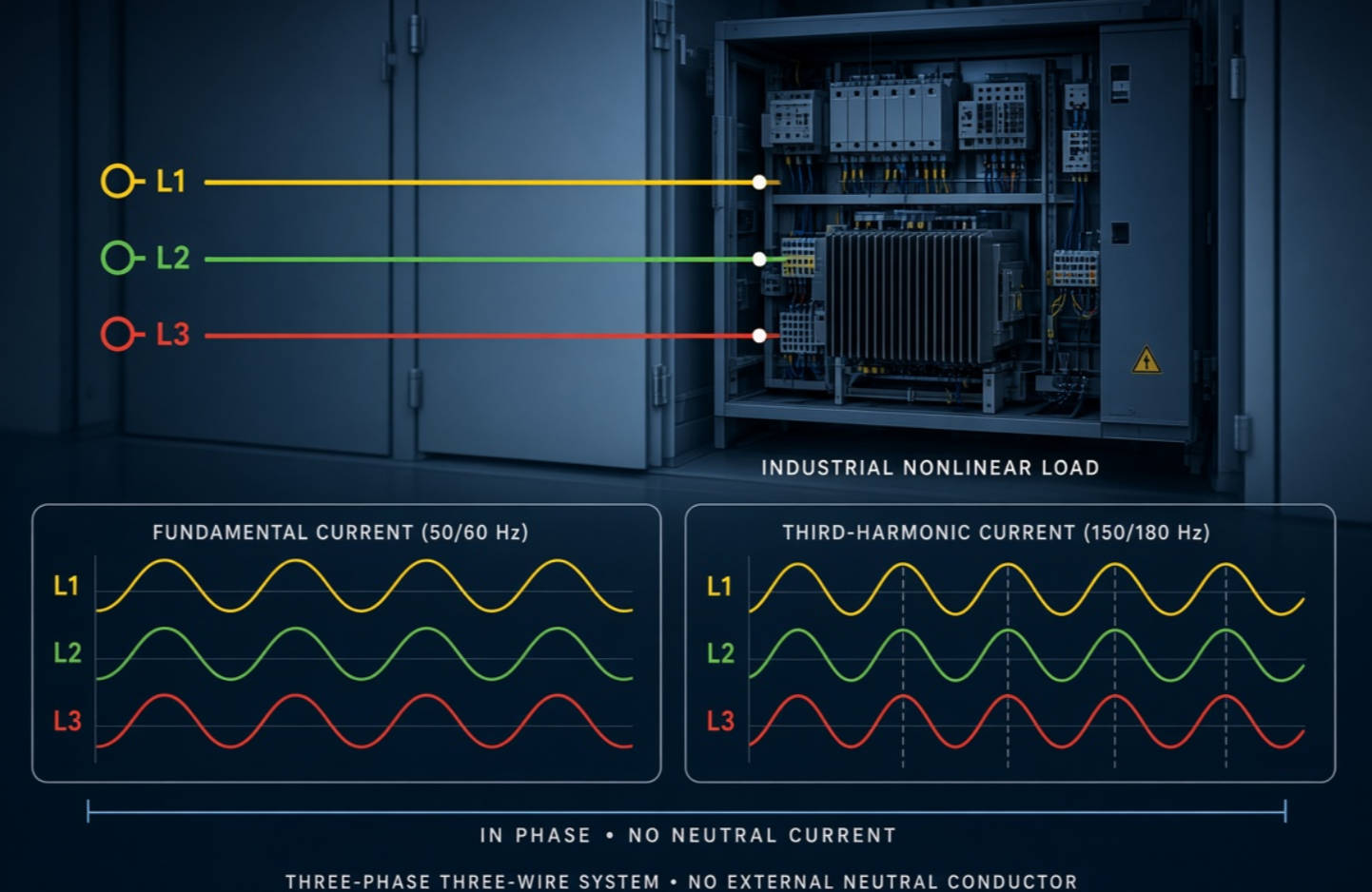
A harmonic is a sinusoidal voltage or current component whose frequency is an integer multiple of the fundamental frequency. In a 50 Hz system, the third harmonic is 150 Hz; in a 60 Hz system, it is 180 Hz.
Third harmonics belong to the broader triplen harmonic family:
| Harmonic order | Typical frequency in 50 Hz systems | Sequence characteristic |
|---|---|---|
| 3rd | 150 Hz | Zero sequence |
| 9th | 450 Hz | Zero sequence |
| 15th | 750 Hz | Zero sequence |
| 21st | 1,050 Hz | Zero sequence |
Triplen harmonics are especially important because the three phase components are normally in phase with each other. Unlike fundamental-frequency currents, which are displaced by 120 degrees and tend to cancel in a balanced three-phase system, balanced third-harmonic currents do not cancel through a neutral conductor. In a 3-phase, 4-wire system, they can add together in the neutral and create severe neutral loading.
In a typical industrial 3-phase, 3-wire system, however, there is no neutral conductor available for zero-sequence third-harmonic current to return through. This changes the visible behavior of the harmonic—but it does not always mean the harmonic source has disappeared.
In an ideal, balanced three-phase, three-wire system, third-harmonic current does not flow in the three supply lines, and third-harmonic voltage does not appear in the line-to-line voltage.
This happens because the third-harmonic phase quantities are in phase:
ia3=ib3=ic3
For a three-wire system, the instantaneous sum of the three line currents must equal zero:
ia+ib+ic=0
If the third-harmonic currents are equal and in phase, their sum would be three times the phase third-harmonic current. With no neutral or other zero-sequence return path, that current cannot flow through the three external lines as a balanced zero-sequence component.
Similarly, line-to-line voltage is calculated by subtracting phase voltages. If identical third-harmonic components exist in each phase-to-neutral voltage, they cancel when one phase is subtracted from another:
Vab3=Van3−Vbn3=0
Therefore, an engineer measuring only line-to-line voltage or three incoming line currents may conclude that no third harmonic exists. That conclusion is valid only for the measured location and operating condition. It should not automatically be extended to internal transformer windings, individual nonlinear loads, capacitor branches, or unbalanced operating conditions.
Third harmonics do not behave identically in every system. Their path depends on transformer winding configuration, grounding method, load balance, and the location of nonlinear loads.
A delta winding provides a closed loop. If third-harmonic voltage components are generated, third-harmonic currents can circulate inside the delta loop.
These circulating currents may not be visible in the external line current measurement. However, they can still create losses and heat within the transformer or connected equipment.
This is one reason why a delta-connected transformer may appear to "block" third harmonics from the upstream system while still experiencing internal harmonic stress.
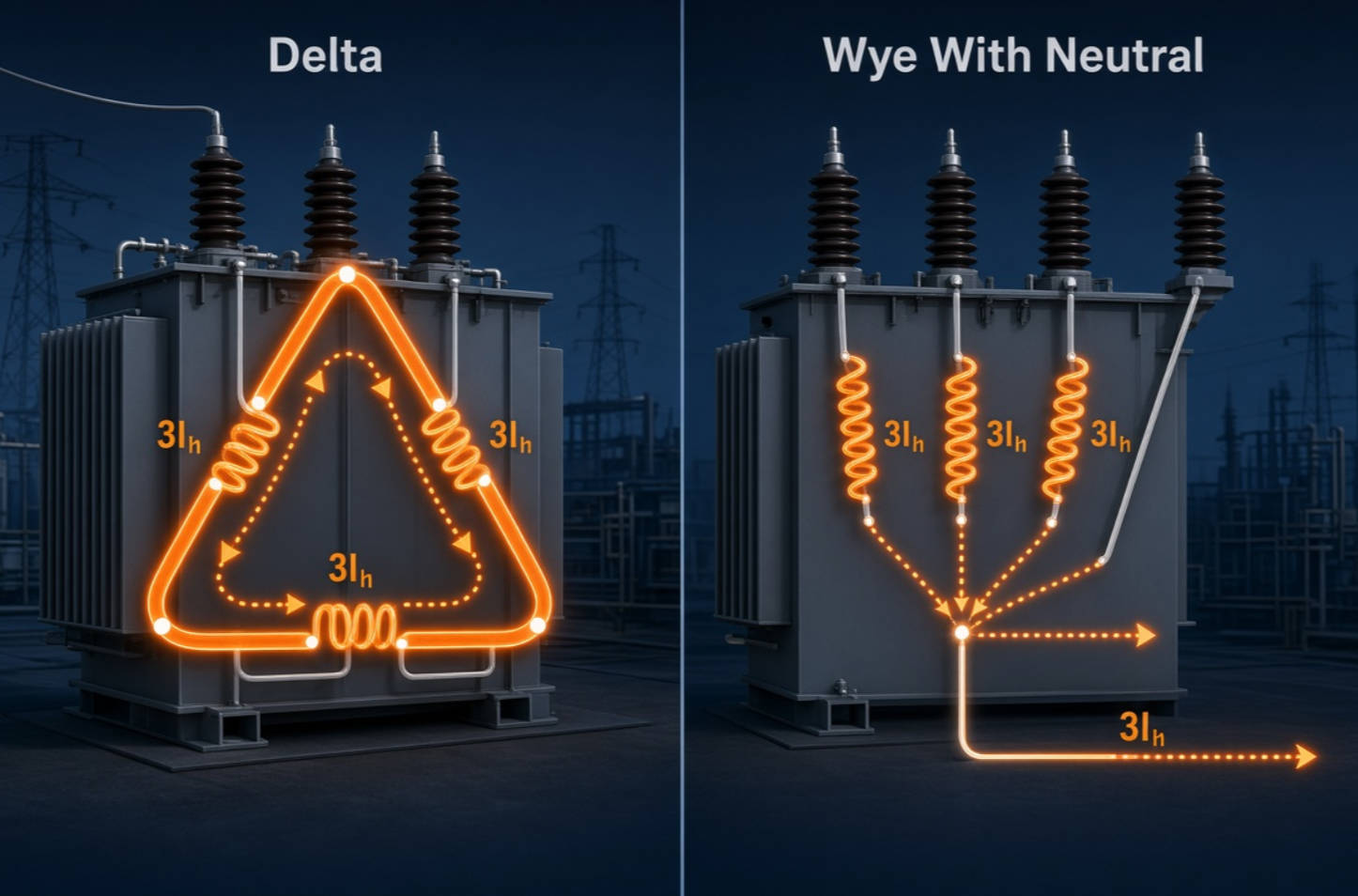
An ungrounded or three-wire wye system does not offer a normal neutral return path for balanced zero-sequence triplen currents. As a result, the third-harmonic current is generally prevented from flowing as a line-current component.
But phase-to-ground voltage distortion, insulation stress, or grounding-related behavior may still require attention, especially when the system includes surge protection, sensitive controls, measurement equipment, or accidental grounding paths.
In a 3-phase, 4-wire system, third-harmonic currents generated by nonlinear single-phase loads can accumulate in the neutral. Common sources include:
- LED lighting drivers
- Computer power supplies
- UPS systems
- Office equipment
- Single-phase rectifier loads
- Data-center IT equipment
- Variable-speed drives with unsuitable input arrangements
Because the triplen components are in phase, the neutral current can become much higher than expected—even when the three fundamental phase currents appear well balanced.
The statement "third harmonic does not exist in a 3-phase, 3-wire system" is too absolute for real industrial networks.
Real facilities are rarely perfectly balanced. Arc furnaces, welding equipment, uneven phase loading, defective rectifier bridges, transformer saturation, asymmetrical firing angles, and inconsistent load operation can create third-harmonic components that include positive- or negative-sequence behavior. These components may then appear in line-current measurements.
In other words, balanced zero-sequence third harmonics are blocked from a standard three-wire path; unbalanced third-harmonic behavior may still be measurable and harmful.
Even when third harmonics are not obvious at the main feeder, they can influence power quality and equipment reliability. This is especially relevant in metallurgical plants, petrochemical facilities, automotive production lines, paper mills, textile factories, and building-material manufacturing sites, where nonlinear loads and reactive power compensation equipment often operate continuously.
Potential consequences include:
- Transformer overheating caused by circulating harmonic currents and additional eddy-current losses.
- Capacitor overcurrent because capacitor impedance decreases as frequency increases.
- Resonance risk when capacitor banks interact with transformer and network inductance.
- Reduced capacitor service life due to sustained harmonic voltage and current stress.
- Nuisance tripping of breakers, fuses, overload relays, and protective devices.
- Control-system malfunctions in PLCs, sensors, automation networks, and process equipment.
- Poor power-factor-correction results when conventional capacitor banks are applied without harmonic assessment.
- Production downtime caused by unexpected trips, failed capacitors, overheated reactors, or unstable voltage.
Harmonic currents increase RMS current and can produce additional thermal stress. The operational impact depends on system impedance, load profile, transformer design, cable configuration, compensation equipment, and the duration of the harmonic condition.
From a power-quality engineering perspective, the most important practical issue is often not whether third harmonic is visible in a three-wire feeder. The key concern is whether harmonic frequencies can be amplified by a capacitor bank.
A conventional capacitor bank supplies reactive power and improves power factor. However, capacitors have lower reactance at higher frequencies:
XC=1/(2πfC)
As frequency rises, capacitive reactance falls. This means capacitors can attract harmonic current, including third-, fifth-, seventh-, and higher-order components.
If the capacitor bank and upstream inductive system create a resonance point near a dominant harmonic order, harmonic current and voltage can increase sharply. The result may include capacitor bulging, blown fuses, contactor damage, reactor overheating, or repeated compensation-system failure.
For this reason, DINGNUO ELECTRIC recommends treating reactive power compensation and harmonic control as a combined engineering task—not as separate equipment purchases.
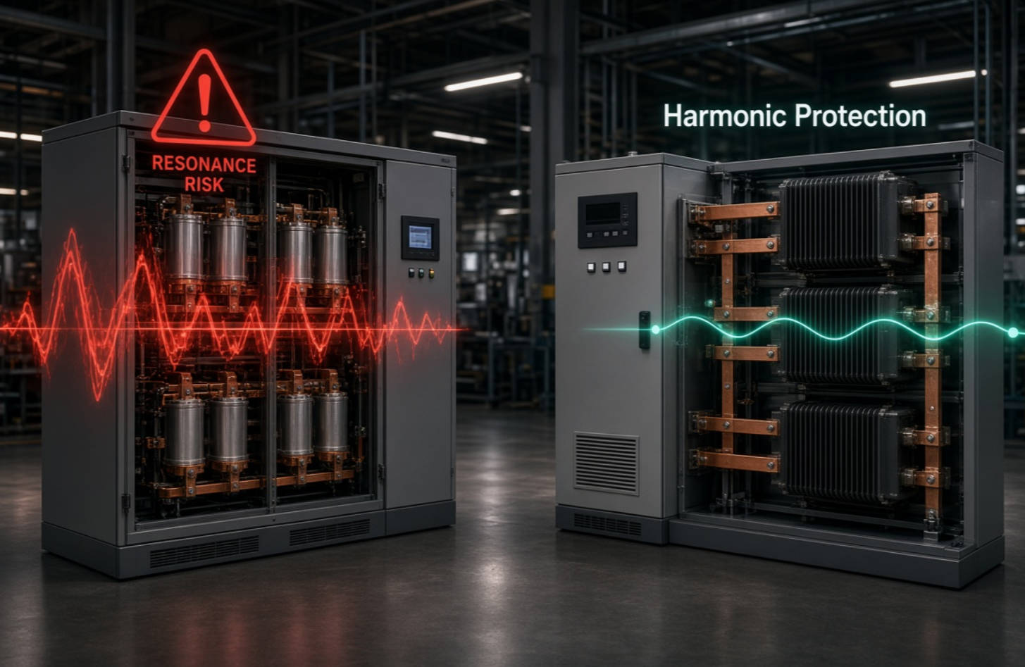
A detuned reactor is installed in series with a capacitor bank to shift the system's resonant frequency away from dominant harmonic frequencies. It also limits harmonic current flowing into the capacitors.
For example, in a 50 Hz network, a properly selected detuned reactor-capacitor combination may be designed with a resonance frequency below the fifth harmonic. This reduces the risk that the capacitor bank will amplify common fifth-harmonic distortion from six-pulse rectifiers and variable-frequency drives.
The required reactor detuning ratio must be selected from actual measurements and network calculations. It should not be chosen solely from a generic catalog recommendation.
A reliable harmonic investigation should be systematic. Measuring only total harmonic distortion at one point is not enough.
Document the electrical architecture before selecting a solution:
- Is the system 3-phase, 3-wire or 3-phase, 4-wire?
- Is there a neutral conductor?
- What transformer vector groups are installed?
- Are delta windings present?
- Is the neutral grounded, impedance grounded, or isolated?
- Where are capacitor banks connected?
- Which feeders supply nonlinear loads?
Transformer connections determine whether triplen harmonics are blocked, circulated, transferred, or converted into other observable effects.
Create a load inventory. Pay special attention to:
- Variable-frequency drives
- Soft starters
- Rectifiers and DC power supplies
- Welding machines
- Induction furnaces and arc furnaces
- UPS systems
- Battery charging systems
- LED lighting circuits
- Data-processing equipment
- Renewable-energy inverters
- Large automation and servo systems
A six-pulse converter commonly produces characteristic fifth and seventh harmonics, while third-harmonic behavior is often more closely associated with zero-sequence paths, transformer magnetizing current, saturation, and single-phase nonlinear loads.
Use a suitable power-quality analyzer to record:
- Voltage THD
- Current THD
- Total demand distortion, where applicable
- Individual harmonic spectrum
- Voltage and current waveform shape
- Fundamental current and peak demand current
- Capacitor-bank current
- Transformer loading and temperature trend
- Neutral current, if a neutral exists
- Time-based operating conditions
Measure at the point of common coupling, the main distribution bus, capacitor bank terminals, transformer secondary, critical load feeders, and any suspected harmonic source.
A single snapshot can be misleading. Capture data during high-load, low-load, startup, and process-transition conditions.
Review whether the existing compensation system operates safely in the measured harmonic environment. Warning signs include:
- Capacitor current above rated value
- Frequent fuse operation
- Excessive reactor temperature
- Swollen capacitor cans
- Abnormal audible noise
- Unstable power factor
- Harmonic levels increasing after capacitor-bank switching
If distortion rises when a capacitor stage is energized, resonance should be investigated immediately.
The solution should match the harmonic source and system condition.
| Power-quality challenge | Typical engineering approach |
|---|---|
| Harmonic-sensitive capacitor bank | Detuned reactor capacitor bank |
| Dynamic reactive power demand | Thyristor-switched compensation or SVG/STATCOM solution |
| Broad, changing harmonic spectrum | Active harmonic filter |
| Dominant fixed harmonic order | Tuned passive filter, subject to system study |
| High neutral current in four-wire network | Neutral assessment, load redistribution, filtering, transformer review |
| Harmonics from large VFD or rectifier loads | Line reactors, DC chokes, multi-pulse solutions, active filters, or low-harmonic drives |
A detailed site study should confirm equipment ratings, short-circuit capacity, harmonic spectrum, existing resonance points, required reactive power, switching requirements, and installation environment.
In industrial power-quality work, the phrase "third harmonic does not exist in a 3-phase, 3-wire system" should be used carefully.
A more accurate engineering conclusion is:
In a balanced three-phase, three-wire circuit, balanced zero-sequence third-harmonic components do not appear in line-to-line voltages or external line currents because there is no neutral return path. However, third-harmonic components can still be generated, circulate in delta-connected windings, affect transformer heating, interact with capacitors, or become measurable under unbalanced conditions.
This distinction helps prevent two common design errors:
1. Installing a standard capacitor bank because third harmonic is not visible at the feeder.
2. Diagnosing harmonic performance using only line-to-line voltage measurements.
A technically sound solution requires an understanding of harmonic source, harmonic path, network impedance, transformer connection, capacitor-bank behavior, and actual load operation.
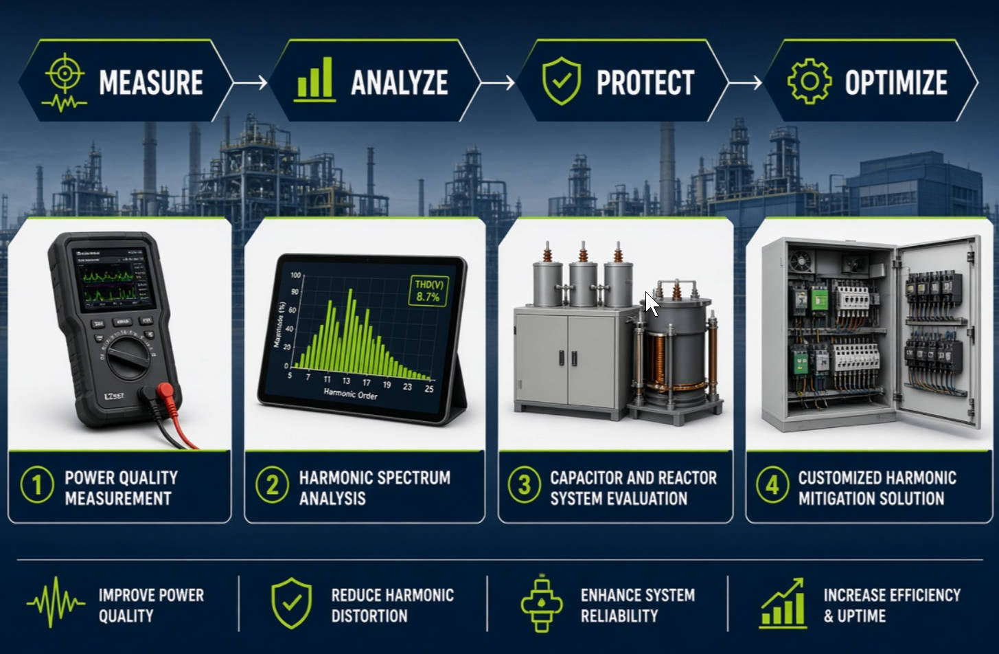
DINGNUO ELECTRIC CO., Ltd. provides power-quality solutions for industrial and infrastructure applications where reactive power demand, harmonic distortion, and electrical reliability must be managed together.
Our product and engineering support can be applied to projects involving:
- Reactive power compensation capacitor banks
- Detuned reactor capacitor systems
- Harmonic filtering solutions
- Low-voltage and medium-voltage power-quality applications
- Dynamic reactive power compensation
- Harmonic analysis and system evaluation
- Customized solutions for complex industrial loads
For facilities in metallurgy, petrochemicals, automotive manufacturing, papermaking, textiles, building materials, and municipal infrastructure, the objective is not merely to install capacitors or reactors. It is to build a stable, efficient, and reliable electrical system that supports continuous production.
If your facility has capacitor failures, transformer overheating, excessive harmonic distortion, unstable power factor, unexplained breaker trips, or concerns about third-harmonic behavior, DINGNUO ELECTRIC can help evaluate the system.
Contact DINGNUO ELECTRIC CO., Ltd. to discuss your load profile, harmonic measurements, capacitor-bank requirements, and customized reactive power compensation or harmonic-control solution. A proper assessment can identify hidden resonance risks before they become costly downtime.
Third-harmonic components may be generated by nonlinear loads or transformer magnetization, but balanced zero-sequence third harmonics do not normally appear in the external line currents or line-to-line voltages of an ideal three-phase, three-wire system.
Third-harmonic phase voltages are in phase with one another. When one phase voltage is subtracted from another to calculate line-to-line voltage, the equal third-harmonic components cancel.
Yes. Delta windings create a closed path that allows triplen harmonic currents to circulate internally. These currents may not appear in the external line current, but they can contribute to transformer losses and heating.
In a four-wire system, third-harmonic currents from each phase are in phase and add in the neutral conductor rather than cancel. This can create excessive neutral current, overheating, voltage distortion, and possible equipment malfunction.
Yes. A conventional capacitor bank can attract harmonic current and may create resonance with the system inductance. Without a harmonic study and suitable detuned reactors or filters, capacitors may suffer overcurrent, overheating, and shortened service life.
Not necessarily. Low voltage THD at one location does not rule out high harmonic current, capacitor overloading, localized resonance, transformer heating, or distortion at another point in the system. Measurements should be taken at multiple locations and operating conditions.
THD typically expresses harmonic content relative to the instantaneous fundamental component. TDD expresses current distortion relative to the maximum demand current over a defined interval. IEEE 519 uses the point of common coupling and considers both voltage distortion and current-distortion criteria in a system-level context.
1. IEEE Standards Association. "IEEE 519-2022: IEEE Standard for Harmonic Control in Electric Power Systems." [Link]
2. Eaton. "IEEE 519 Standard – What Do I Need to Know? Where Do I Start?" [Link]
3. Electrical Engineering Portal. "What Are Triplen Harmonics and Where Do They Happen?" [Link]
4. Schneider Electric. "A High 3rd Harmonic Current Can Cause a High Neutral Current." [Link]
5. YT Electric. "Is There 3rd Harmonics in 3 Phase 3 Wire System?" [Link]
6. Eaton. "Harmonic Analysis Study in the Power System." [Link]


