
Views: 298 Author: Dingnuo Electric Publish Time: 2026-08-19 Origin: Site


Content Menu
● What Are Harmonics in Electrical Power Systems?
● What Are Even Order Harmonics?
>> Why Do Even Harmonics Occur?
● What Are Odd Order Harmonics?
>> Positive-, Negative-, and Zero-Sequence Harmonics
● Even vs. Odd Order Harmonics: Key Differences
● How Harmonics Damage Capacitor Banks and Reactors
● A Practical Harmonic Assessment Process
>> 1. Measure at the Right Electrical Location
>> 2. Identify the Dominant Harmonic Orders
>> 3. Check Resonance Before Adding Capacitors
>> 4. Confirm Results After Commissioning
● Choosing the Right Harmonic Mitigation Solution
● Improve Your Power Quality with DINGNUO ELECTRIC
● FAQ
>> 1. What is the difference between even and odd order harmonics?
>> 2. Which harmonic orders are most common in industrial facilities?
>> 3. Can a capacitor bank reduce harmonics?
>> 4. Why do capacitors fail in systems with harmonic distortion?
>> 5. What is the purpose of a detuned reactor?
>> 6. Is THD alone enough to select a harmonic filter?
Even and odd order harmonics are voltage or current components whose frequencies are integer multiples of the fundamental power frequency. In a 50 Hz electrical system, the 2nd harmonic is 100 Hz, the 3rd harmonic is 150 Hz, the 5th harmonic is 250 Hz, and so on. Understanding the difference between even and odd order harmonics is essential when selecting capacitor banks, detuned reactors, passive harmonic filters, or active harmonic filters for industrial power-quality systems.
At DINGNUO ELECTRIC CO., Ltd., we work with industrial users facing harmonic-related capacitor overheating, transformer overload, nuisance tripping, unstable automation equipment, and power-factor-correction failure. In practical projects, the correct solution does not begin with selecting a product. It begins with identifying the harmonic spectrum, load characteristics, network impedance, and the electrical point where power quality is evaluated.
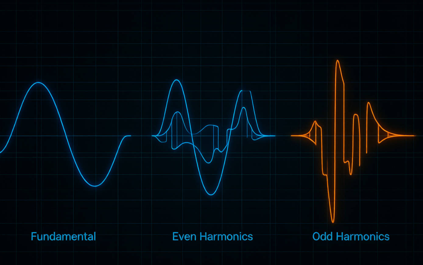
An ideal AC power system delivers a smooth sine wave at its rated fundamental frequency: usually 50 Hz or 60 Hz. Harmonics are additional sinusoidal frequency components superimposed on that fundamental waveform.
For example, in a 50 Hz system:
| Harmonic Order | Frequency | Classification |
|---|---|---|
| Fundamental | 50 Hz | Base Supply Frequency |
| 2nd Harmonic | 100 Hz | Even-Order Harmonic |
| 3rd Harmonic | 150 Hz | Odd-Order Harmonic |
| 5th Harmonic | 250 Hz | Odd-Order Harmonic |
| 7th Harmonic | 350 Hz | Odd-Order Harmonic |
| 11th Harmonic | 550 Hz | Odd-Order Harmonic |
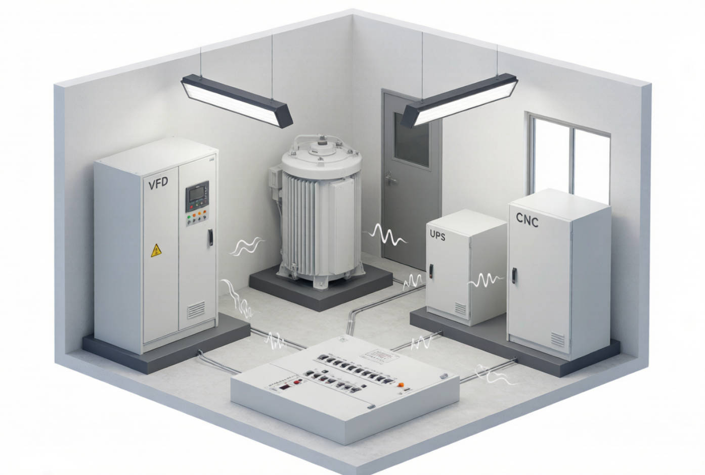
Harmonics are mainly generated by nonlinear loads. Unlike linear loads, nonlinear equipment does not draw current in the same smooth waveform as the supply voltage. Instead, it draws current in pulses or distorted patterns, injecting harmonic currents back into the electrical network.
Common harmonic-producing equipment includes:
- Variable frequency drives (VFDs)
- Servo drives and CNC equipment
- Rectifiers and DC power supplies
- UPS systems
- Arc furnaces and welding equipment
- Battery chargers
- LED lighting drivers
- Data-center and telecom power equipment
- Renewable-energy inverters
The result is a distorted current waveform and, depending on network impedance, a distorted voltage waveform. This can reduce reliability across the entire distribution system—not only at the load that created the distortion.
Even order harmonics are harmonics with an even number order, such as the 2nd, 4th, 6th, 8th, and 10th harmonics.
In a 50 Hz network, their frequencies include 100 Hz, 200 Hz, 300 Hz, and 400 Hz. In a 60 Hz system, the 2nd harmonic is 120 Hz, the 4th is 240 Hz, and so forth.
Under normal balanced operating conditions, even harmonics are generally much lower than odd harmonics. When significant even-order harmonics appear, they often indicate that the waveform has become asymmetrical between its positive and negative half cycles.
From an engineering perspective, even harmonics often signal an abnormal condition rather than routine operation. Typical causes include:
- DC offset or DC injection into an AC network
- Unbalanced rectifier operation
- Asymmetrical semiconductor switching
- Transformer core saturation
- Faulty power electronic components
- Uneven positive and negative waveform clipping
- Equipment malfunction or control-system errors
The 2nd harmonic is particularly important in transformer applications. A high second-harmonic current component may occur during transformer energization because of inrush current and core saturation. Protective relays often use second-harmonic restraint logic to distinguish transformer inrush from an internal transformer fault.
Even harmonics should not be ignored simply because they are less common. Their presence can indicate a developing equipment fault, saturation issue, or unwanted DC component.
Potential consequences include:
- Transformer overheating and additional core losses
- Protection-relay misoperation
- Motor torque pulsation
- Increased noise and vibration
- Reduced equipment service life
- Unstable operation of sensitive electronic controls
When a power-quality measurement shows a notable 2nd harmonic, maintenance teams should investigate the source rather than treating it as a normal background condition.
Odd order harmonics are harmonics with odd-numbered orders, such as the 3rd, 5th, 7th, 9th, 11th, and 13th. They are the most common harmonics in commercial and industrial electrical systems.
The most frequently encountered harmonic orders are:
- 3rd harmonic: Often generated by single-phase electronic loads and switch-mode power supplies
- 5th harmonic: Commonly associated with six-pulse rectifiers and VFDs
- 7th harmonic: Also typical of six-pulse power-conversion equipment
- 11th and 13th harmonics: Often linked to higher-pulse converters and industrial drive systems
For a typical six-pulse rectifier, characteristic harmonics can be estimated using:
h=np±1
Where:
- h is the harmonic order
- p is the pulse number of the converter
- n is a positive integer
For a six-pulse converter, this produces characteristic orders such as the 5th, 7th, 11th, 13th, 17th, and 19th harmonics.
Odd harmonics do not all behave in the same way in a three-phase system.
| Harmonic orders | Sequence behavior | Typical system impact |
|---|---|---|
| 3rd, 9th, 15th | Zero sequence | Can accumulate in neutral conductors |
| 5th, 11th, 17th | Negative sequence | Can create reverse rotating fields in motors |
| 7th, 13th, 19th | Positive sequence | Rotate in the normal phase sequence |
The 3rd harmonic and its multiples are often called triplen harmonics. In four-wire three-phase systems, triplen harmonic currents from each phase are in phase with each other in the neutral conductor. Rather than cancelling, they add together.
This is why a neutral conductor can overheat even when individual phase currents appear acceptable.
The 5th harmonic is especially harmful to motors because it produces a negative-sequence rotating magnetic field. This field opposes the normal motor rotation, contributing to torque pulsation, heat, vibration, and reduced efficiency.
| Factor | Even-order harmonics | Odd-order harmonics |
|---|---|---|
| Typical orders | 2nd, 4th, 6th, 8th | 3rd, 5th, 7th, 11th, 13th |
| Frequency in a 50 Hz system | 100 Hz, 200 Hz, 300 Hz | 150 Hz, 250 Hz, 350 Hz, 550 Hz |
| Common occurrence | Less common in healthy systems | Common in industrial and commercial systems |
| Typical indication | Waveform asymmetry, DC offset, saturation, equipment fault | Nonlinear loads and power-electronic conversion |
| Major risks | Transformer saturation, relay issues, abnormal equipment condition | Capacitor overload, neutral overheating, motor losses, resonance |
| Primary response | Diagnose the source and check equipment condition | Measure spectrum and apply a coordinated mitigation solution |
In most industrial plants, odd harmonics—especially the 5th, 7th, 11th, and 13th—are the main focus of harmonic-control design. However, high even harmonics deserve prompt investigation because they can reveal a fault or asymmetrical operating condition that standard power-factor correction will not resolve.
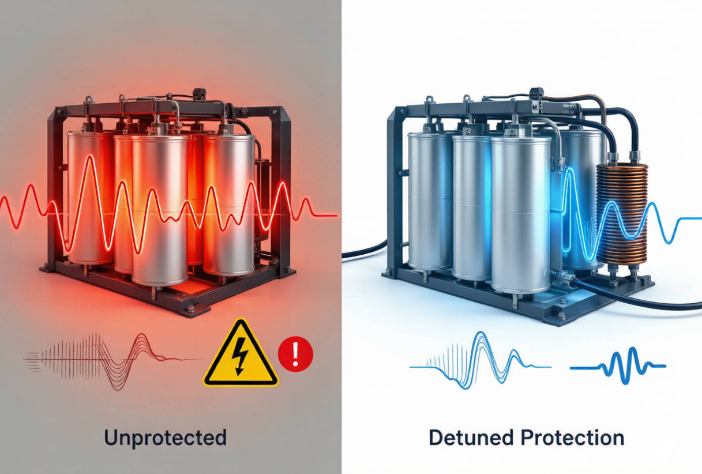
Capacitor banks are widely used to improve power factor and reduce reactive-power demand. However, capacitors have lower impedance at higher frequencies. This means they may attract harmonic current rather than simply supplying reactive power at the fundamental frequency.
Without proper design, harmonic current can cause:
- Capacitor overheating
- Bulging capacitor cases
- Fuse operation or contactor failure
- Dielectric stress and shortened capacitor life
- Excessive current in busbars and cables
- Amplification of existing harmonic distortion
- Resonance between the capacitor bank and system inductance
This is why installing a conventional capacitor bank in a harmonic-rich system can be risky. If the system resonance frequency aligns with a dominant harmonic frequency, the network may amplify that harmonic instead of reducing it.
A detuned reactor connected in series with the capacitor bank shifts the resonant frequency below the dominant harmonic order. This helps prevent harmonic amplification and protects the capacitor bank from excessive harmonic current. Schneider Electric notes that detuned reactors are used to prevent resonance-driven harmonic amplification and avoid capacitor overloading.
For example, when the 5th harmonic is dominant in a 50 Hz system, the capacitor-reactor combination is commonly designed with a resonant frequency below 250 Hz. The exact reactor detuning factor must be selected from measured harmonic conditions, capacitor rating, grid voltage, transformer impedance, and target reactive-power compensation.
The most effective harmonic-control projects follow a measurement-first approach. Do not select an active harmonic filter, passive filter, capacitor bank, or reactor solely from transformer capacity or installed load kW.
Start with measurements at the point of common coupling (PCC), the main incoming panel, major distribution boards, and near suspected nonlinear loads.
Measure:
- Voltage THD (THDv)
- Current THD (THDi)
- Individual harmonic spectrum
- Maximum demand and load variation
- Power factor and reactive power
- Neutral current
- Transformer loading
- Voltage unbalance
- Capacitor-bank current and temperature
IEC 61000-4-7 provides guidance for measuring harmonics and interharmonics in power systems and applies to instruments measuring spectral components up to 9 kHz on 50 Hz and 60 Hz supply systems.
A total harmonic distortion number alone is not enough. Two facilities may both show 8% THDi but require entirely different solutions.
For example:
- A high 3rd harmonic may require neutral-conductor assessment and attention to single-phase nonlinear loads.
- A strong 5th and 7th harmonic pattern often points to six-pulse drives or rectifiers.
- A broad spectrum with rapidly changing loads may favor an active harmonic filter.
- A concentrated and stable harmonic source may be suitable for a properly engineered passive filter.
Before expanding reactive-power compensation, evaluate the risk of parallel or series resonance. This is especially important in plants with large VFD groups, arc furnaces, welding systems, or existing capacitor banks.
A detuned reactor protects the capacitor bank, but it is not automatically a complete harmonic-compliance solution. It primarily prevents resonance and reduces stress on capacitors. If harmonic current must be actively reduced to meet a utility, equipment, or project-specific target, an active harmonic filter or engineered passive filter may also be needed.
A complete solution includes post-installation verification. Re-measure harmonic levels, capacitor current, power factor, loading conditions, and temperature after commissioning.
This step confirms whether the selected solution works under actual production conditions—not only under an assumed design load.
The best solution depends on the harmonic spectrum, load stability, required compensation capacity, system voltage, and project objective.
| Condition | Recommended approach |
|---|---|
| Low harmonic levels, stable loads | Standard capacitor bank after verification |
| Capacitor bank exposed to 5th/7th harmonics | Detuned capacitor bank with series reactor |
| High and changing harmonic currents | Active harmonic filter (AHF) |
| Strong, stable, known harmonic order | Tuned passive harmonic filter |
| Dynamic reactive-power demand | Static var generator (SVG) or dynamic compensation system |
| High 3rd harmonic and neutral current | Load review, neutral assessment, and targeted filtering |
| Transformer saturation or high 2nd harmonic | Investigate DC bias, inrush, asymmetry, and equipment condition |
At DINGNUO ELECTRIC, our engineering approach combines reactive-power compensation and harmonic control rather than treating them as separate issues. The objective is to improve power factor while maintaining capacitor reliability, avoiding resonance, reducing harmonic stress, and supporting stable operation across industrial loads.
Our capacitor and reactor solutions are applicable to demanding industries including metallurgy, petrochemical processing, automotive manufacturing, paper production, textiles, building materials, and municipal infrastructure projects.
Consider a manufacturing plant with multiple VFD-driven pumps, fans, and conveyors. The facility adds a conventional automatic capacitor bank to improve power factor. Soon afterward, operators report repeated capacitor fuse failures and unusually high capacitor-bank temperature.
A power-quality survey finds significant 5th and 7th harmonic currents from the VFDs. The new capacitor bank created a low-impedance path at frequencies close to the system's resonant point, increasing harmonic current through the capacitors.
A better approach is to:
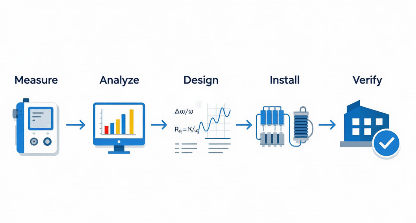
1. Measure harmonic voltage and current under representative production loads.
2. Confirm the dominant 5th and 7th harmonic spectrum.
3. Calculate system resonance based on transformer impedance, short-circuit capacity, cable parameters, and capacitor kVAr.
4. Replace or redesign the bank as a detuned capacitor bank with correctly selected reactors.
5. Add an active harmonic filter if measured distortion remains above the project or utility requirement.
6. Verify capacitor current, THDv, THDi, power factor, and temperature after commissioning.
This approach addresses the root cause rather than repeatedly replacing damaged capacitors.
If your facility experiences capacitor failures, transformer heating, excessive neutral current, unstable drives, poor power factor, or harmonic-related equipment trips, DINGNUO ELECTRIC can help evaluate the issue and recommend a coordinated solution.
Contact our engineering team with your single-line diagram, transformer rating, existing capacitor-bank data, major nonlinear-load list, and power-quality measurements. We can help you select suitable capacitor banks, detuned reactors, harmonic filters, and reactive-power compensation solutions for safer and more reliable electrical operation.
Even-order harmonics have orders such as the 2nd, 4th, and 6th. Odd-order harmonics include the 3rd, 5th, 7th, and higher odd numbers. Odd harmonics are generally more common in industrial systems, while notable even harmonics often indicate waveform asymmetry, DC offset, saturation, or equipment malfunction.
The 5th, 7th, 11th, and 13th harmonics are common in facilities with VFDs, rectifiers, UPS systems, and other power-electronic loads. Third harmonics are also important in systems with many single-phase nonlinear loads.
A standard capacitor bank is designed primarily for reactive-power compensation, not harmonic reduction. In a harmonic-rich network, it can amplify harmonics through resonance. A detuned capacitor bank, passive harmonic filter, or active harmonic filter should be selected based on measurement and engineering analysis.
Capacitors can attract harmonic current because their impedance decreases as frequency rises. Excess harmonic current increases thermal, voltage, and dielectric stress. Resonance can further magnify the problem and lead to overheating, fuse failure, bulging, or premature capacitor failure.
A detuned reactor is installed in series with a capacitor bank. It shifts the capacitor-reactor resonance frequency below a dominant harmonic order, helping prevent harmonic amplification and protecting capacitors from excessive harmonic current.
No. THD is a useful indicator, but harmonic-order data, load behavior, system impedance, transformer capacity, capacitor-bank configuration, and the PCC requirement are also needed. Two systems with the same THD may need different mitigation methods.
1. International Electrotechnical Commission. "IEC 61000-4-7: Electromagnetic Compatibility—Testing and Measurement Techniques—General Guide on Harmonics and Interharmonics Measurements and Instrumentation." Available at: [IEC Webstore]. [webstore.iec]
2. Eaton. "IEEE 519 Standard: What Do I Need to Know?" Available at: [Eaton]. [eaton]
3. Schneider Electric. "Decoding Detuned Reactors: What and Why." Available at: [Schneider Electric Blog]. [blog.se]
4. Eaton. "What Is the Difference Between a Tuned and De-Tuned Filter?" Available at: [Eaton Expert Video]. [videos.eaton]
5. International Electrotechnical Commission. "IEC 61000-4-7 Standard Preview." Available at: [IEC 61000-4-7 Document]. [elstandard]
6. YT Electric. "What Are Even and Odd Order Harmonics?" Available at: [YT Electric]. [ytelect]


