
Views: 237 Author: Dingnuo Electric Publish Time: 2026-10-07 Origin: Site


Content Menu
● Understanding Three-Phase Voltage Unbalance
>> What Does Voltage Unbalance Mean?
>> Common Causes in Industrial Facilities
>> Why Small Imbalances Matter to Motors
● Measuring and Diagnosing Voltage Unbalance
>> Calculate Three-Phase Voltage Unbalance
>> Understand the Sequence-Based Measurement
>> Follow a Practical Troubleshooting Workflow
>> An Illustrative Textile-Plant Scenario
● Choosing the Right Power Quality Solution
>> Match the Equipment to the Problem
>> What Capacitors and Reactors Can Achieve
>> When Active Compensation Needs Evaluation
>> Keep Protection Separate From Compensation
>> Specify Results Before Purchasing
>> 1. What Causes Three-Phase Voltage Unbalance?
>> 2. What Voltage Unbalance Is Acceptable for Motors?
>> 3. Can a Capacitor Bank Fix Voltage Unbalance?
>> 4. Do Detuned Reactors Eliminate Harmonics?
>> 5. Is Current Imbalance the Same as Voltage Unbalance?
>> 6. What Information Should I Send DINGNUO?
>> Discuss Your Power Quality Requirements
>> References
Three-phase voltage unbalance can overheat motors, destabilize production, and expose weaknesses in an industrial electrical network. Understanding its causes—and separating it from current imbalance, poor power factor, and harmonic distortion—is essential before selecting capacitors, reactors, or other power quality equipment.
At DINGNUO ELECTRIC CO., Ltd., our focus is capacitor and reactor manufacturing, reactive power compensation, and harmonic control. This guide takes an engineering-first approach: measure the problem, identify its origin, and match the solution to the evidence rather than treating every disturbance as a compensation issue.

A balanced three-phase supply has equal fundamental voltage magnitudes and phase angles separated by 120 degrees. Voltage unbalance occurs when these magnitudes, phase relationships, or both depart from that condition.
The distinction between voltage and current matters. Unevenly distributed single-phase loads create current imbalance. Those unequal currents can then produce different voltage drops across the supply impedances, resulting in voltage unbalance.
However, current imbalance does not automatically prove that the incoming supply is unbalanced. Motor winding defects, load characteristics, and downstream connection problems can also produce unequal currents.
For maintenance teams, the key question is not simply, "Which phase carries more current?" It is, "Where does the imbalance begin, and under what operating conditions?"
Several conditions deserve investigation:
- Uneven single-phase loading across lighting, heating, office, and auxiliary circuits.
- Loose terminals, deteriorated contactors, damaged cables, or unequal conductor impedances.
- Blown fuses or failed elements in power factor correction equipment.
- Unbalanced incoming utility voltage or transformer-related problems.
- Intermittent faults and switching events that change phase loading.
Harmonics are a related but distinct issue. Nonlinear loads can distort voltage and current waveforms, yet harmonic distortion and fundamental-frequency voltage unbalance require separate measurements.
In metallurgy and petrochemical plants, changing process loads can make disturbances time-dependent. In automotive, paper, textile, and building-material production, a feeder-level problem may affect multiple motors even when the main switchboard appears normal.
Negative-sequence voltage produces a magnetic field rotating opposite to the motor's normal field. The resulting currents increase heating and can contribute to torque pulsation and mechanical stress.
A useful warning is that motor current imbalance can be approximately six to ten times the voltage unbalance. This is a diagnostic rule of thumb, not a fixed prediction for every motor or operating point.
Practical consequences include:
- Hotter windings and reduced insulation life.
- Increased losses and reduced operating efficiency.
- Vibration, nuisance trips, and reduced production reliability.
- A need to reduce allowable motor loading.
For conventional three-phase motors, a commonly cited benchmark is no more than 1% voltage unbalance at the terminals. Above that level, assess derating using the applicable motor guidance and manufacturer instructions. Do not treat 1% as a universal acceptance limit for every electrical device.
A practical magnitude-based calculation uses the three line-to-line RMS voltages:
1. Measure VAB, VBC, and VCA at the same operating condition.
2. Calculate their average.
3. Find the largest absolute deviation from that average.
4. Divide that deviation by the average and multiply by 100.
Voltage unbalance (%)=100×Maximum absolute deviation/Average line-to-line voltage
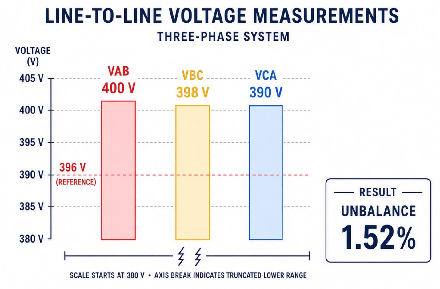
For example, suppose the measurements are 400 V, 398 V, and 390 V. Their average is 396 V, and the maximum deviation is 6 V. The calculated voltage unbalance is approximately 1.52%.
That result deserves investigation at a loaded motor. It does not identify the cause, determine the correct capacitor rating, or establish the required motor derating by itself.
A more complete assessment uses the voltage unbalance factor:
VUF (%)=100×Negative-sequence voltage/Positive-sequence voltage
Unlike the simple magnitude calculation, sequence analysis accounts for phase relationships. A suitable three-phase power quality analyzer can provide this information.
Always record the calculation method. A sequence-based VUF and a maximum-deviation percentage are not interchangeable, so comparing them without identifying the method can produce misleading conclusions.
Live testing requires qualified electrical personnel, appropriate protective equipment, and site-specific safety procedures. Isolate equipment before intrusive inspection or repair.
1. Establish a baseline. Record phase voltages, currents, loading, power factor, and harmonic distortion during representative production conditions.
2. Compare locations. Measure at the incoming supply, relevant switchboards, affected feeders, and motor terminals to locate where conditions worsen.
3. Correlate events. Check whether the disturbance follows a compressor start, welding cycle, capacitor step, or other repeatable event.
4. Inspect the identified circuit. Check phase loading, connections, fuses, contactors, cables, and capacitor-bank condition.
5. Apply a targeted correction. Repair defects or redistribute loads before adding compensation equipment.
6. Verify performance. Repeat the measurements under comparable loading and retain before-and-after records.
A single handheld reading can miss intermittent problems. Monitoring should cover the operating cycles responsible for the complaint, rather than an arbitrary short test window.
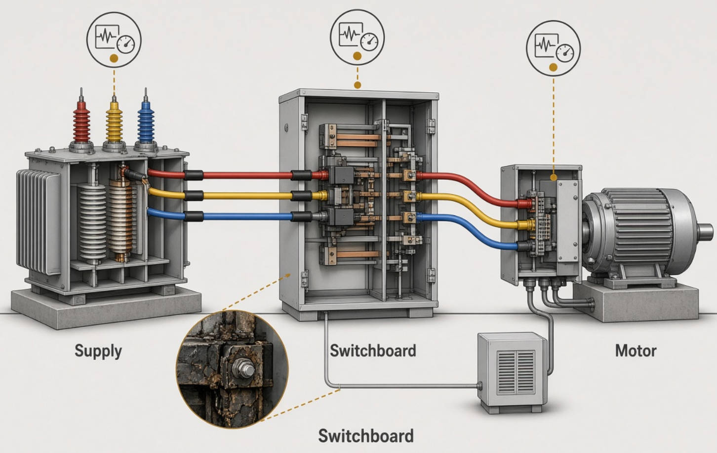
Consider a hypothetical textile plant reporting overheated motors during evening production. The main supply remains relatively balanced, but measurements at one motor feeder show higher unbalance when auxiliary single-phase heaters operate.
The investigation finds uneven heater distribution and a deteriorated connection. The correct initial actions are to redistribute the heater circuits and repair the connection—not purchase a larger capacitor bank.
After those repairs, the team separately evaluates reactive demand and harmonic loading. This sequence avoids confusing three different problems and creates a measurable basis for any subsequent equipment investment.
This scenario is illustrative, not a documented DINGNUO customer result. Actual performance must be established through site measurements.
Capacitors and reactors are valuable components, but their functions must be clearly distinguished from phase-balancing functions.
| Measured problem | Appropriate first response | Important limitation |
|---|---|---|
| Unequal single-phase loading | Redistribute circuits and verify feeder capacity | Balanced reactive compensation does not redistribute active loads |
| Loose connection or failed fuse | Repair the defect and retest | Compensation cannot replace a sound electrical connection |
| Low displacement power factor | Engineer appropriately sized capacitor compensation | Better power factor does not guarantee balanced voltages |
| Capacitor-bank resonance risk | Evaluate a properly designed detuned reactor-capacitor bank | Detuning is not equivalent to removing all harmonics |
| Persistent dynamic current imbalance | Evaluate purpose-designed active balancing equipment | Capability depends on topology, controls, and current rating |
| Unbalanced incoming supply | Investigate with the utility or upstream system operator | Local compensation may not resolve the upstream cause |
The engineering priority is to correct the dominant mechanism first. Equipment selection should follow that diagnosis, not substitute for it.
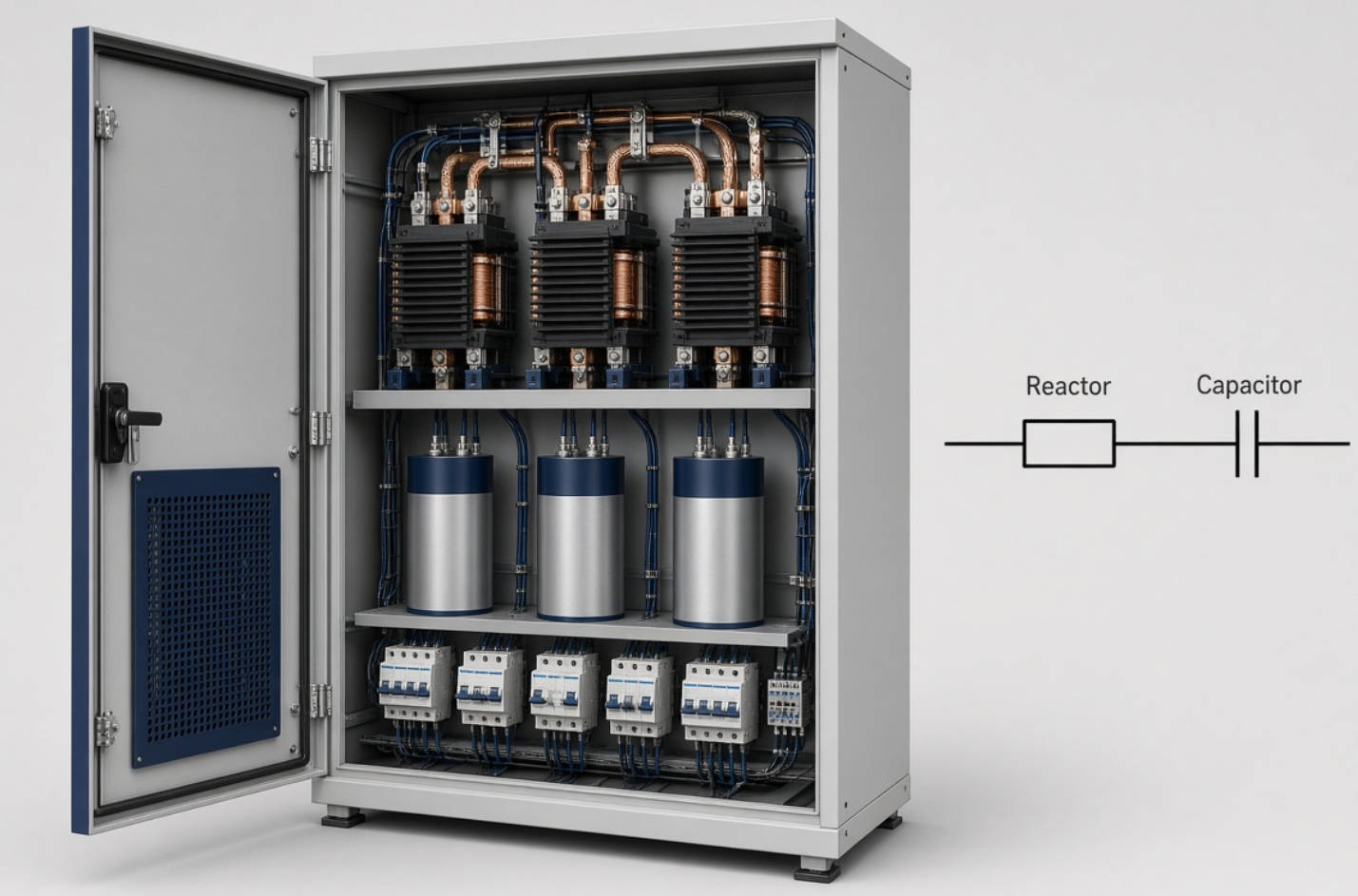
Power factor correction capacitors supply reactive power locally. Where appropriately applied, they can reduce upstream reactive current and associated distribution losses.
However, a conventional balanced three-phase capacitor bank does not independently correct unequal active-power demand across phases. It should not be marketed as a universal cure for three-phase voltage unbalance.
Capacitors also interact with network inductance. In a system containing harmonic-producing loads, this interaction can create resonance and amplify harmonic currents or voltages.
A detuned reactor changes the reactor-capacitor branch's resonant characteristics to reduce this risk. Selection requires attention to the actual harmonic spectrum, supply impedance, operating frequency, capacitor voltage duty, and expected current loading.
Avoid selecting a reactor percentage solely because it is common in another factory. A suitable design must also consider changing capacitor steps and alternative operating configurations.
Some static var generators and active harmonic filters offer phase-current balancing functions. These capabilities are product-specific; they should not be assumed from the equipment category alone.
Ask the supplier to confirm:
- Whether the equipment supports three-wire or four-wire applications.
- Whether it compensates negative-sequence current, neutral current, or both.
- How current capacity is shared among reactive compensation, harmonic filtering, and balancing.
- What performance is achievable under the measured supply conditions.
Reducing downstream current imbalance may improve voltage balance when unequal voltage drops are the cause. It does not guarantee correction of an already-unbalanced upstream voltage source.
For DINGNUO projects, capacitor and reactor selection should remain grounded in this distinction. Any broader solution should be assessed against verified equipment capabilities and project-specific acceptance criteria.
Compensation is not a replacement for motor protection. A system can achieve a satisfactory overall power factor while one motor still experiences damaging phase conditions. Review phase-loss, voltage-unbalance, and overload protection with the responsible engineer, using the motor manufacturer's requirements and the actual operating profile.
Also separate equipment protection from process continuity. A correctly configured protective device may stop a motor to prevent damage, but repeated trips still require root-cause investigation. Bypassing that protection to maintain production can turn a manageable electrical defect into a more expensive equipment failure. Record trip timing alongside analyzer data to support the investigation.
A useful enquiry package includes the single-line diagram, system voltage and frequency, transformer rating, load schedule, existing compensation details, and recorded power quality data.
Define how success will be measured: voltage unbalance at critical terminals, phase-current loading, power factor, harmonic levels, and equipment thermal performance.
Compare results at similar production loads. Without that context, an apparent improvement may reflect a quieter shift rather than a better solution.
Request supporting calculations, applicable test documentation, commissioning requirements, and maintenance guidance. Product certifications or performance guarantees should appear in purchasing decisions only when the relevant documents have been verified.
Common causes include uneven single-phase loading, unequal circuit impedance, deteriorated connections, failed compensation components, and upstream supply problems. Measure both voltage and current at several locations to distinguish the source from the symptom.
A commonly used benchmark is 1% or less at the motor terminals. Above that, review manufacturer instructions and applicable derating guidance. The relevant limit depends on the equipment and operating conditions, not just a general website recommendation.
Not generally. Standard capacitor banks primarily compensate reactive power. They do not redistribute uneven active loads or repair faulty connections. Replacing failed capacitor-bank components can help when that failure caused the imbalance.
No. Their primary role in compensation banks is to manage resonance risk and protect the reactor-capacitor arrangement under specified conditions. Broader harmonic mitigation requires a separate assessment and, where necessary, additional filtering measures.
No. Voltage unbalance describes the supply voltage relationship; current imbalance describes unequal phase currents. They influence each other through network impedance and load behavior, but one measurement cannot replace the other.
Send your system voltage, frequency, transformer details, single-line diagram, load profile, existing capacitor-bank information, and available power quality measurements. Include when overheating, trips, or production disturbances occur so the enquiry reflects actual operating conditions.
Contact DINGNUO ELECTRIC CO., Ltd. with your measurements and project requirements to discuss capacitor, reactor, reactive compensation, and harmonic-control options. Start with a defined problem and measurable acceptance criteria—not an assumed equipment size.
1. Original: Shanghai Yingtong Electric Co., Ltd., ["The Impact of Voltage 3 Phase-Unbalanced"], November 25, 2024. Used as the starting topic and structural reference. The retrieved text lacks a displayed calculation formula, conflates several power quality issues, and makes broad equipment claims without site-specific qualification. Its supplier credentials have not been transferred to DINGNUO. [ytelect]
2. Motors: U.S. Department of Energy, ["Eliminate Voltage Unbalance," Motor Systems Tip Sheet #7], November 2012. Supports the maximum-deviation calculation, common causes, motor effects, monitoring recommendations, and the 1% motor-terminal benchmark with derating considerations. [docs.nlr]
3. Measurement: Schneider Electric, ["How Current or Voltage Unbalance Is Calculated in PowerLogic…"]. Explains the IEC sequence-based voltage unbalance factor and the NEMA magnitude-deviation approach. Supports the distinction between these measurement methods. [se]
4. Resonance: Eaton, ["Power Factor Correction and Harmonic Resonance: A Volatile Mix"]. Supports discussion of capacitor-network resonance, harmonic amplification, and engineered mitigation. [eaton]
5. Reactors: Powerside, ["Safeguard Against Resonance with Low Voltage, Detuned Capacitor Banks"], June 2026. Supports the explanation of detuning and the need to consider harmonic-producing loads. [powerside]
6. Amplification: ABB, ["Rule Change: Department of Energy Requirements"]. Supports the qualified rule of thumb that 1% voltage unbalance may produce approximately 6–10% current unbalance. [search.abb]
7. Company: DINGNUO's manufacturing focus and industry positioning come from the company description supplied in the brief. No independent certifications, customer testimonials, installation results, or performance guarantees were supplied.


