
Views: 243 Author: Dingnuo Electric Publish Time: 2026-10-12 Origin: Site


Content Menu
● Why Wind Farms Need Reactive Power Compensation
● What Is an SVG for Wind Farms?
>> How an SVG Controls Reactive Power
>> What an SVG Cannot Guarantee by Itself
● What Is a Capacitor Bank for Wind Farms?
>> How Capacitor Banks Provide Compensation
>> Why Reactors and Switching Design Matter
● SVG vs Capacitor Bank for Wind Farms: Side-by-Side Comparison
● Voltage-Sag Performance: The Most Important Technical Difference
● Grid Compliance Starts at the Connection Point
>> Request a Composite Capability Curve
● Harmonic Control: Neither Technology Is an Automatic Solution
>> Capacitor Banks Require Resonance Assessment
>> SVG Harmonic Performance Requires Clear Boundaries
● Cost Comparison: Evaluate the Whole Compensation System
● A Hybrid SVG and Capacitor Bank Can Be the Better Architecture
● A Practical Selection Workflow for Wind-Farm Developers
>> Step 1: Define the Required Operating Envelope
>> Step 2: Establish Existing Turbine Capability
>> Step 3: Model the Complete Electrical Network
>> Step 4: Compare Three Architectures
>> Step 5: Verify Controls and Acceptance Tests
● Specify the Right Solution With DINGNUO ELECTRIC
>> 1. Is an SVG Better Than a Capacitor Bank for Wind Farms?
>> 2. Can a Capacitor Bank Replace an SVG?
>> 3. Do Modern Wind Turbines Still Need External Compensation?
>> 4. Does an SVG Eliminate Wind-Farm Harmonics?
>> 5. How Should a Wind-Farm Capacitor Bank Be Sized?
>> 6. Can an SVG and Capacitor Bank Operate Together?
● Sources
Choosing an SVG vs capacitor bank for wind farms is not simply a question of which device supplies reactive power more cheaply. The real decision is whether your wind farm needs steady-state compensation, fast voltage support, or a coordinated combination of both. A capacitor bank provides economical capacitive compensation, while a static var generator offers continuously controlled capacitive and inductive output. Modern wind turbine converters can also contribute, so additional equipment should be selected around the capability of the entire plant—not considered in isolation.
For DINGNUO ELECTRIC CO., Ltd., a manufacturer specializing in capacitors, reactors, reactive power compensation, and harmonic control, the practical starting point is the customer's electrical system. Equipment selection should follow the connection requirements, operating conditions, and network studies.
This guide compares the technologies through an engineering and procurement lens, including a voltage-sag example, a hybrid compensation strategy, and a practical specification checklist.
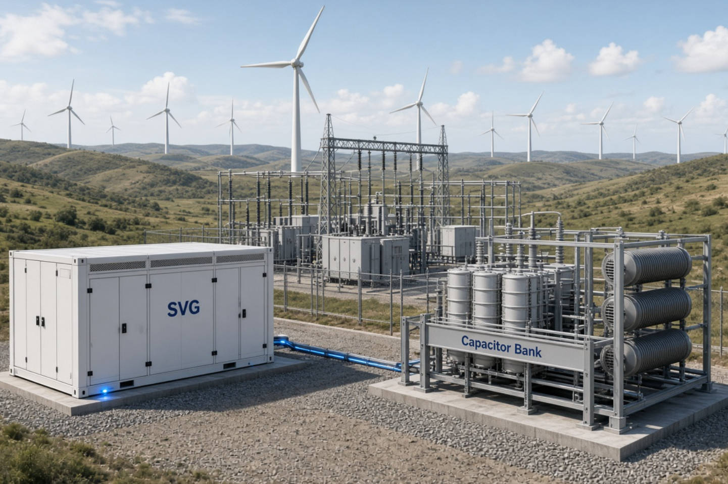
Wind farms must manage both active power and reactive power. Active power delivers useful energy. Reactive power supports voltage and interacts with transformers, collector cables, turbine converters, and the external network.
The plant's reactive capability at the point of interconnection differs from the capability stated at individual turbine terminals. Internal electrical infrastructure changes the reactive power balance, and turbine converter capability can vary with voltage, active power output, temperature, and current limits.
Consequently, a wind farm may need capacitive support in one operating condition and inductive absorption in another. Low-generation operation deserves particular attention: cable charging and other internal reactive sources can affect the plant's net exchange even when active power output is small.
The key procurement principle is coordination: evaluate turbine capability, external compensation, and plant controls together.
A static var generator, or SVG, uses power electronics to control reactive current. In this article, SVG refers to converter-based shunt compensation commonly described in utility applications as a STATCOM, or static synchronous compensator. Procurement documents should confirm the actual topology and performance rather than rely on terminology alone.
A voltage-source converter operates through a coupling impedance to inject or absorb reactive current. Within its operating limits, it can move continuously between capacitive and inductive output.
This makes converter-based compensation suitable for changing voltage conditions. Utility STATCOM systems offer millisecond-scale switching and fast reactive response, although switching speed is not the same as the guaranteed closed-loop response of the complete wind farm.
A purchase specification should therefore define measurement location, response time, settling time, overshoot, and operating limits.
Installing an SVG does not automatically ensure fault ride-through, eliminate all harmonics, or resolve weak-grid instability.
Its effectiveness depends on converter current limits, protection settings, network strength, turbine behavior, and control interactions. Dynamic voltage support must also account for how equipment prioritizes active and reactive current during disturbances.
A capacitor bank consists of capacitor units arranged to supply capacitive reactive power. Banks may be fixed or divided into switched stages.
Capacitor banks can supply a relatively steady portion of the plant's capacitive requirement. Their reactive output depends on terminal voltage:
Qcap=Qrated(V/Vrated)2
Therefore, their output falls significantly during a voltage sag. Wind-farm control design must account for this voltage-squared relationship when calculating the contribution of each stage.
Reactors may serve different functions, including limiting switching current or forming part of a detuned or tuned filter arrangement.
These functions should not be confused. A reactor selected for switching duty is not automatically suitable for harmonic filtering. Likewise, adding capacitors without checking system impedance can amplify existing harmonic voltages. Published utility compensation studies explicitly assess harmonic amplification and capacitor overload protection.
For a capacitor and reactor manufacturer such as DINGNUO ELECTRIC, component selection should therefore form part of a system-level design.
| Selection factor | SVG / STATCOM | Capacitor bank |
|---|---|---|
| Reactive output | Continuously controlled within its capability | Fixed output or discrete switched stages |
| Output direction | Capacitive and inductive | Capacitive; separate equipment is needed for absorption |
| Dynamic behavior | Fast converter-based response | Depends on switching technology and stage control |
| Low-voltage performance | Current-limited; reactive power still declines with voltage | Reactive power declines with voltage squared |
| Main application | Dynamic voltage support and variable compensation | Bulk capacitive compensation |
| Harmonic considerations | Converter emissions and network interactions require assessment | Resonance and harmonic loading require assessment |
| Plant integration | Requires coordinated dynamic controls | Requires stage sequencing and switching coordination |
These distinctions follow converter operating principles, capacitor voltage dependence, and plant-level compensation guidance. They do not establish a universal winner: the correct choice depends on the required operating envelope.
Comparing nameplate MVAr ratings alone can hide a major performance difference.
Consider an illustrative 10 MVAr capacitor bank operating at 0.7 per-unit voltage:
Qcap=10×0.72=4.9 MVAr
The bank supplies only 49% of its rated reactive power under that condition.
For an illustrative converter rated to deliver 10 MVAr at nominal voltage, maintaining the same rated reactive current at 0.7 per-unit voltage would give approximately:
Qconverter≈10×0.7=7.0 MVAr
This comparison assumes balanced conditions, retained current capability, no overload allowance, and no blocking or protection intervention. It is a simplified engineering illustration—not a vendor performance guarantee. Capacitor output follows voltage squared, while converter performance is governed by voltage and available current.
The procurement implication is straightforward: request an SVG's reactive current-versus-voltage envelope and disturbance behavior, not just its nominal MVAr rating.

A wind farm's compliance assessment should use the location specified by its connection agreement. Turbine-terminal ratings do not establish what the complete plant can deliver at the required measurement point.
For certain US interconnections, NERC guidance discusses the dynamic reactive capability requirements associated with FERC Order No. 827, including a 0.95 leading-to-0.95 lagging power factor range unless the transmission provider establishes another range. This is not a universal requirement for every country or project.
A useful plant-level assessment should show:
- Maximum capacitive and inductive capability.
- Capability across the active power operating range.
- Relevant voltage and temperature conditions.
- Contributions from turbines and external compensation.
- The effect of internal network equipment.
NERC recommends documenting composite capability at the specified measurement point, while modeling guidance recognizes the operating limits of individual converters and other plant reactive devices.
This prevents a common purchasing error: buying sufficient nominal compensation while leaving a gap in actual plant capability.
Capacitors alter network impedance. Depending on the electrical system, they can interact with inductance and increase harmonic voltage or current.
A harmonic assessment should examine background distortion, turbine emissions, network configurations, capacitor stage combinations, and component loading. Detuning and tuned filtering require deliberate design; they are not interchangeable labels. Utility case documentation demonstrates the importance of checking existing harmonics before installing compensation.
Modern STATCOM designs can operate with limited need for external harmonic filters. That does not mean every SVG replaces a dedicated harmonic filter.
When comparing quotations, ask suppliers to distinguish between:
1. The converter's own harmonic emissions.
2. Any separately offered harmonic compensation function.
3. The plant's expected distortion at the connection point.
4. The network conditions used to establish performance.
A proposal should specify what is guaranteed and under which conditions.
Capacitor banks are candidates for economical bulk compensation, while converter-based systems provide controllability and dynamic support. However, no universal cost ratio applies across voltage levels, ratings, sites, and performance requirements. Interconnection guidance recognizes that external static and dynamic devices may provide an economical alternative or supplement to turbine converter capability.
For procurement, compare complete installed systems rather than component prices alone.
Include the following quotation items:
- Compensation equipment and associated switchgear.
- Transformers, reactors, protection, and controls.
- Installation and commissioning scope.
- Guaranteed losses across representative operating points.
- Cooling and auxiliary power requirements.
- Maintenance, spare parts, and technical support.
- Modeling, testing, and compliance documentation.
This checklist is a decision framework, not a claim that one technology always has lower lifetime cost. Suppliers should substantiate their figures using comparable assumptions.
The choice does not always have to be SVG or capacitor bank.
A hybrid arrangement can allocate relatively steady capacitive demand to capacitor stages and leave a converter to manage the faster-changing residual requirement. Additional reactors may be needed where inductive absorption requirements exceed the converter's available range.
STATCOM systems can incorporate switched or fixed capacitors and reactors to extend their overall compensation range. Plant-level guidance also recognizes combinations of inverter capability and static reactive devices.
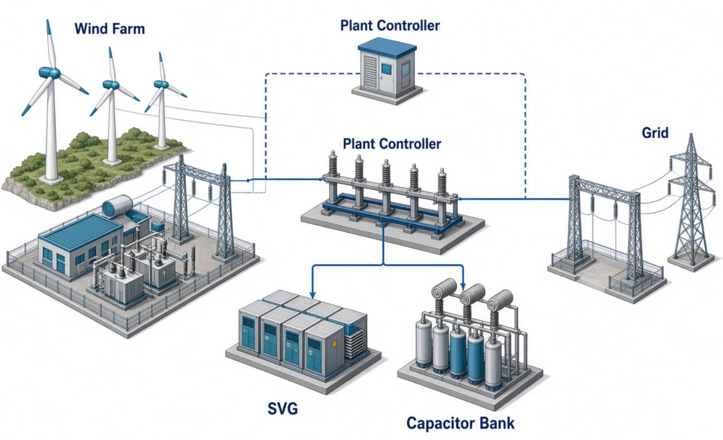
A practical control strategy should avoid using all available converter capability for a persistent baseline requirement when static equipment could carry part of that duty.
However, switching capacitors at every small voltage change is also undesirable. Stage sequencing, deadbands, delays, and converter setpoints should be coordinated to avoid unnecessary switching and conflicting control actions.
Validate the combined response at plant level, with in-plant reactive devices operating normally—not merely through separate factory demonstrations.

Document the connection-point voltage range, reactive capability, dynamic response, and disturbance requirements. Include low-generation and zero-generation conditions where applicable.
Obtain turbine capability curves and control models. Confirm current limits and whether available reactive capability changes with active power, terminal voltage, or temperature.
Include collector cables, transformers, existing compensation, and credible network configurations. Determine the residual compensation requirement after accounting for the plant's internal sources and demands.
Evaluate:
1. Turbine capability with capacitor-bank support.
2. Turbine capability with SVG support.
3. A coordinated hybrid arrangement.
Each option should satisfy the same performance criteria before its commercial value is compared.
Specify plant-level voltage response, reactive capability verification, and model validation. Test documentation should distinguish equipment performance from the behavior of the complete connected plant.
DINGNUO ELECTRIC CO., Ltd. supplies capacitor and reactor products, reactive power compensation, and harmonic-control solutions for industrial and infrastructure applications.
For a wind-farm inquiry, provide the single-line diagram, connection requirements, turbine capability data, collector-system details, and available harmonic measurements.
Ask DINGNUO ELECTRIC to assess the capacitor and reactor configuration within your wider compensation design. Where dynamic support is required, define SVG interface requirements with the project's system integrator. The objective is a technically justified solution—not simply the largest equipment package.
An SVG is better suited to continuously variable, bidirectional reactive support. A capacitor bank suits bulk capacitive compensation. The preferred solution depends on the plant's dynamic requirements and existing turbine capability.
Only when the complete plant can meet its required performance without the SVG. A capacitor bank does not provide equivalent continuous control, and its output falls with voltage squared.
Sometimes. Turbine converters can provide reactive power, but their capability and the plant's internal network determine whether additional static or dynamic equipment is necessary.
Not automatically. STATCOM designs may need limited filtering for their own operation, but plant-wide harmonic performance still requires a separate assessment and explicit guarantees.
Size it from the plant's operating envelope, internal reactive balance, turbine capability, voltage conditions, and dynamic requirements—not from a power-factor correction calculation alone.
Yes. A coordinated hybrid can combine bulk capacitive compensation with dynamic support. Its controls and overall capability should be verified at the plant's specified measurement point.
1. National Renewable Energy Laboratory and Sandia National Laboratories. "Reactive Power Interconnection Requirements for PV and Wind Plants." Technical report discussing plant-level reactive capability, turbine converter limitations, and supplementary compensation equipment. [osti]
2. Hitachi Energy. "Static Compensator (STATCOM)." Technical overview of converter-based reactive power compensation, dynamic voltage support, and configurations incorporating capacitors and reactors. [hitachienergy]
3. North American Electric Reliability Corporation. "Reliability Guideline: Inverter-Based Resource Interconnection Requirements Improvements." Guidance addressing interconnection requirements, reactive capability, voltage control, and plant-level performance. [nerc]
4. Hitachi Energy. "Reactive Power Compensation at RTE." Technical case documentation covering compensation design, harmonic assessment, and capacitor-bank protection. [publisher.hitachienergy]
5. Western Electricity Coordinating Council. "Inverter-Based Resources Power Plant Modeling and Validation Guideline." Guidance on plant modeling and validation, including converter capability limits under different operating conditions. [wecc]
6. Schweitzer Engineering Laboratories. "Reactive Power Control System for Wind Farm Application Using IEC 61850." Technical paper describing wind-farm reactive power control and the voltage-dependent output of capacitor banks. [selinc]


