
Views: 262 Author: Dingnuo Electric Publish Time: 2026-09-20 Origin: Site


Content Menu
● What Is Power Quality Measurement?
● Why Power Quality Measurement Matters in Industrial Facilities
>> Common Symptoms of Poor Power Quality
● Which Parameters Should Be Measured?
● Where Should You Measure Power Quality?
>> 1. Point of Common Coupling
>> 2. Main Incoming Distribution Panel
>> 3. Capacitor Bank or Compensation Cabinet
● How to Conduct a Power Quality Measurement Correctly
>> Step 1: Define the Operating Problem
>> Step 2: Select a Suitable Analyzer
>> Step 3: Follow Electrical Safety Procedures
>> Step 4: Configure Ratios and Verify Direction
>> Step 5: Measure for a Representative Period
>> Step 6: Analyze Trends, Events, and Harmonic Spectrum
● Harmonics, Capacitors, and the Risk of Resonance
>> Why Conventional Capacitor Banks Can Fail
>> Choosing a Corrective Solution
● Power Quality Standards: What They Mean for Your Site
● A Practical Industrial Example
● How DINGNUO ELECTRIC Supports Power Quality Improvement
● FAQ
>> 1. What is the purpose of power quality measurement?
>> 2. How long should a power quality measurement last?
>> 3. What is the difference between voltage THD and current THD?
>> 4. Why do capacitor banks fail in systems with harmonics?
>> 5. Do I need a reactor with a capacitor bank?
>> 6. Can improving power factor solve harmonic problems?
>> 7. Where is the best place to measure harmonics?
>> 8. What information should be included in a power quality report?
Power quality measurement is the systematic process of monitoring electrical parameters to determine whether a facility's power supply and load behavior are stable, efficient, and compliant with applicable standards. For industrial sites, accurate measurement is the foundation for solving harmonics, voltage fluctuation, reactive power penalties, capacitor failures, overheating, and unexpected equipment trips.
At DINGNUO ELECTRIC CO., Ltd., we support power users, panel builders, and industrial operators with power quality compensation and harmonic-control solutions, including capacitors, reactors, filtering components, and reactive power compensation systems. Our experience across metallurgy, petrochemical processing, automotive production, paper, textile, building-materials manufacturing, and municipal projects shows that a successful solution always begins with reliable site data—not assumptions.
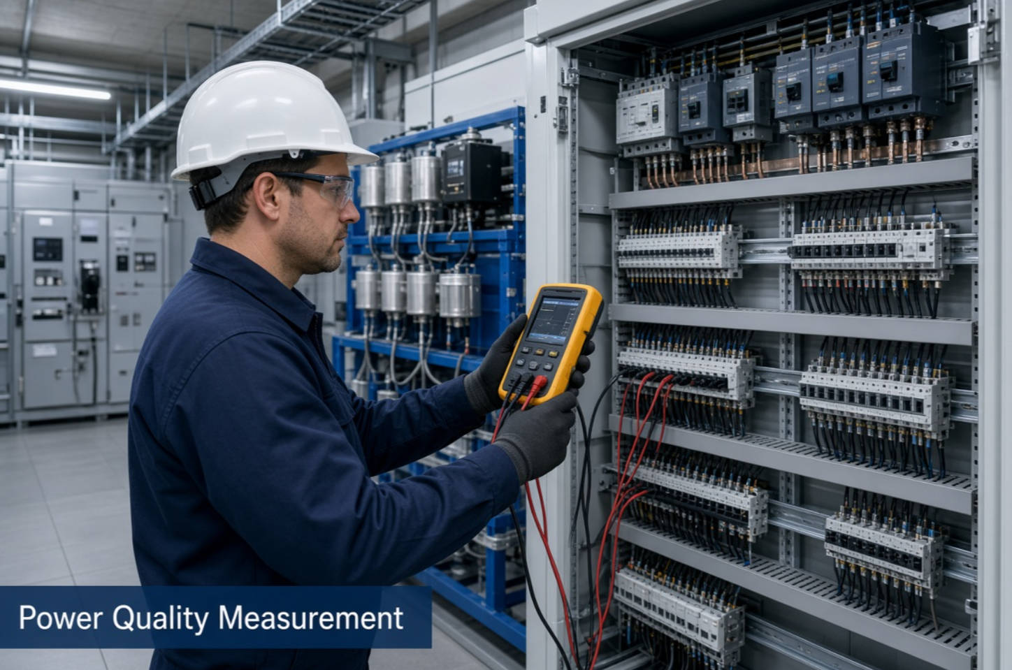
Power quality measurement is the collection, recording, and interpretation of electrical data from a power system. It helps engineers determine whether voltage, current, frequency, waveform, and power factor remain within acceptable operating conditions.
In practical terms, power quality measurement answers critical questions:
- Is the incoming voltage stable?
- Are nonlinear loads creating excessive harmonic current?
- Is the facility paying for unnecessary reactive power?
- Are capacitor banks operating safely?
- Why do variable-frequency drives, PLCs, motors, or electronic equipment trip unexpectedly?
- Is a power quality issue coming from the utility supply, the customer's loads, or both?
A complete measurement process does not end when an analyzer is connected. It includes defining the problem, selecting the correct measurement point, configuring the instrument properly, collecting data across representative operating conditions, interpreting results, and designing corrective actions.
For industrial facilities, this process can reveal hidden causes of energy loss and equipment stress before they become failures, shutdowns, or costly replacement projects.
Modern factories rely heavily on power-electronic equipment. Variable-frequency drives, rectifiers, welding machines, UPS systems, LED lighting, automated production lines, data systems, and inverter-based equipment can improve productivity. However, they can also distort current waveforms and create complex power quality challenges.
A site may appear normal during a brief inspection while still experiencing severe problems during production peaks, machine starts, welding cycles, or shifts with high nonlinear-load demand. This is why professional power quality measurement should capture representative operating conditions rather than only a single moment.
Power quality problems often appear as operational symptoms before their electrical cause is recognized. Common warning signs include:
- Frequent tripping of circuit breakers or protective devices
- Overheated cables, transformers, neutral conductors, or switchgear
- Repeated capacitor-bank fuse failures
- Capacitor bulging, leakage, or shortened service life
- High electricity bills caused by low power factor or reactive energy charges
- Malfunctioning PLCs, sensors, control systems, and communication equipment
- Unstable motor operation or abnormal vibration
- Transformer overheating under loads that appear to be within capacity
- Flickering lights or voltage dips during large-load switching
- High total harmonic distortion, often called THD
- Reduced production uptime and increased maintenance costs
These symptoms should not be treated independently. A failed capacitor, for example, may not be a capacitor-quality issue. It may be the result of resonance, excessive harmonic current, incorrect reactor selection, an unsuitable switching method, or a compensation system designed without real load measurements.
A reliable power quality assessment should evaluate more than power factor. While power factor is important, it cannot by itself explain harmonic distortion, voltage events, load imbalance, or waveform problems.
The exact measurement scope depends on the facility, voltage level, load profile, and complaint. However, the following parameters are typically essential.
| Parameter | What It Shows | Why It Matters |
|---|---|---|
| Voltage magnitude | Whether supply voltage remains near its declared level | Under-voltage and over-voltage can affect motors, controls, and process equipment |
| Current magnitude | Actual loading of feeders, transformers, and equipment | Reveals overload patterns and abnormal demand |
| Frequency | Stability of the AC supply frequency | Important for systems sensitive to frequency variation |
| Power factor | Relationship between real power and apparent power | Helps identify reactive power demand and potential penalty exposure |
| Reactive power | Inductive or capacitive power demand, usually measured in kvar | Supports correct capacitor-bank and compensation-system sizing |
| Active power | Useful power consumed, usually measured in kW | Establishes real production energy demand |
| Apparent power | Total electrical capacity demand, measured in kVA | Important for cable, transformer, and switchgear capacity |
| Voltage THD | Distortion in the voltage waveform | High levels can affect sensitive equipment and indicate system interaction |
| Current THD | Harmonic distortion created by connected loads | Helps assess harmonic source strength and filter requirements |
| Individual harmonics | Amplitude of harmonic orders such as 5th, 7th, 11th, and 13th | Essential for harmonic diagnosis and reactor/filter design |
| Voltage unbalance | Unequal phase-voltage conditions | Can cause motor heating and reduced motor performance |
| Current unbalance | Unequal current loading across phases | May indicate uneven loads, wiring issues, or phase imbalance |
| Voltage dips and swells | Short-duration decreases or increases in voltage | Helps investigate process interruptions and equipment resets |
| Transients | Rapid, high-frequency voltage events | May damage electronics or cause unexplained failures |
| Flicker | Visible instability in lighting caused by voltage variation | Relevant in sites with fluctuating loads such as welding or large motors |
International measurement standards provide methods for obtaining repeatable and comparable results. IEC 61000-4-30 defines measurement methods for power quality parameters in AC systems and includes categories such as supply voltage, frequency, flicker, voltage dips, interruptions, unbalance, harmonics, interharmonics, current magnitude, and current harmonics. The standard recognizes Class A and Class S measurement methods, with Class A intended for advanced, high-confidence applications.
Selecting the wrong measurement location can produce misleading conclusions. A measurement at one panel may show acceptable conditions while a downstream feeder serving sensitive equipment experiences a serious problem.
The best location depends on the purpose of the investigation.
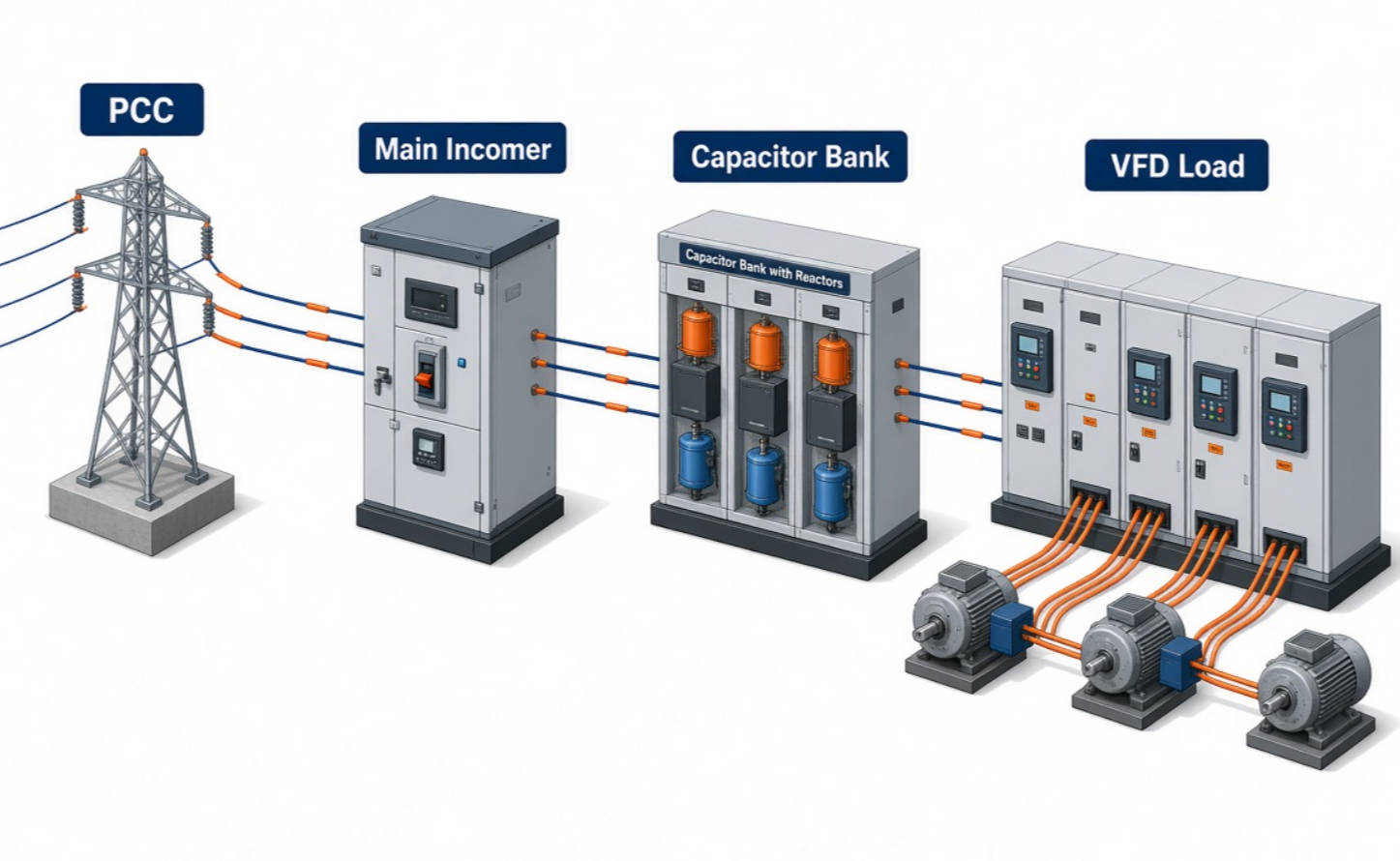
The point of common coupling, often called the PCC, is commonly used to assess the relationship between a facility and the public distribution network. It is especially important when determining whether harmonic distortion, voltage deviation, or power quality complaints may involve the supply side or the customer side.
IEEE 519 addresses harmonic control in electrical power systems and evaluates harmonic performance at the point of common coupling. Its scope includes static power converters used across industrial and commercial power systems.
Measurement at the main incoming panel provides a facility-wide view. It is useful for assessing total power consumption, maximum demand, total reactive power, overall power factor, and the combined harmonic impact of all connected loads.
This location is often the first choice when a factory reports:
- Utility power-factor penalties
- High total current harmonic distortion
- Main transformer overheating
- Repeated main-breaker trips
- Need for centralized reactive power compensation
Measurements at the capacitor bank help verify whether the compensation system is operating as designed. Engineers should check capacitor current, reactor condition, switching behavior, detuning performance, harmonic content, and the relationship between compensation steps and changing load demand.
This is particularly important when capacitors fail frequently or when power factor remains poor despite an installed automatic compensation cabinet.
For factories with variable-frequency drives, rectifiers, induction furnaces, UPS systems, DC power supplies, welding lines, or large automation systems, measurements on individual feeders can identify major harmonic sources.
This approach helps separate the dominant source from the overall system response. It also helps prevent a common mistake: installing a general-purpose capacitor bank without understanding whether the connected load requires detuned reactors, passive harmonic filters, active harmonic filters, or a hybrid solution.
Power quality measurement should be treated as an engineering task, not simply an instrument-reading exercise. Incorrect current-transformer ratios, reversed current probes, wrong phase sequence, or incomplete monitoring periods can lead to wrong conclusions and unnecessary investment.
Start with a clear description of the issue. Record when it occurs, which equipment is affected, and what operating conditions are present.
Useful questions include:
- Does the problem occur during startup, peak production, or shutdown?
- Is it linked to a specific machine, line, or shift?
- Did the issue begin after installing VFDs, UPS systems, welding equipment, or new motors?
- Are capacitor failures occurring at the same time as increased nonlinear loading?
- Is the issue seasonal, intermittent, or continuous?
A good investigation begins with production context. An analyzer can show abnormal values, but operating history helps explain why those values occur.
For formal diagnosis, dispute resolution, high-value industrial projects, or compliance-oriented reporting, a Class A power quality analyzer is generally the preferred choice. Class A instruments are designed to provide reliable and repeatable measurements when the same signal is measured by different compliant instruments.
The instrument should be appropriate for the required voltage level, current range, safety category, recording duration, communication method, and measurement objective.
Power quality measurement may require work near energized equipment. Only qualified personnel should perform the connection and verification process.
Essential precautions include:
- Use appropriately rated personal protective equipment
- Follow lockout/tagout procedures where applicable
- Confirm voltage ratings before connection
- Use correctly rated voltage leads and current probes
- Verify phase sequence and probe orientation
- Keep measurement leads secure and protected from mechanical damage
- Follow the facility's electrical safety program and local regulations
Safety is not an optional part of data quality. A rushed or unsafe installation may also result in poor connections, incorrect readings, and unreliable analysis.
Before recording data, confirm:
- Voltage transformer ratio, if voltage transformers are used
- Current transformer ratio
- Current-probe direction
- Phase labels and phase sequence
- Nominal system voltage
- Nominal frequency
- Wiring configuration, such as three-phase three-wire or three-phase four-wire
- Measurement interval and event thresholds
A reversed current probe can make a load appear to be generating power. An incorrect CT ratio can distort current, power, and harmonic results. These basic setup errors are among the most common reasons for misleading reports.
A short test may miss the event that matters. The measurement period should reflect the facility's operating cycle.
For example:
- A continuously operating plant may require several days of logging.
- A plant with weekday production variation may require a full week.
- A batch process may require monitoring across several complete batches.
- An issue linked to motor starts or welding cycles may require event-triggered recording with high-resolution waveform capture.
IEC 61000-4-30 specifies defined measurement aggregation concepts for relevant parameters, helping make results comparable across compliant instruments and reports.
Do not rely only on a single maximum value. Review time trends and correlate them with plant activity.
An effective analysis should examine:
- Average, maximum, and minimum voltage
- Power factor trends by time of day
- Reactive power demand
- Current loading patterns
- Voltage and current THD
- Individual harmonic orders
- Harmonic changes when equipment starts or stops
- Voltage events, including dips, swells, and interruptions
- Phase imbalance
- Capacitor current and switching behavior
- Possible resonance conditions
Harmonics are voltage or current components at integer multiples of the fundamental frequency. In a 50 Hz system, the 5th harmonic is 250 Hz and the 7th harmonic is 350 Hz. In a 60 Hz system, the 5th harmonic is 300 Hz and the 7th harmonic is 420 Hz.
Nonlinear loads draw current in pulses rather than in a smooth sinusoidal waveform. This distorted current can create voltage distortion as it flows through system impedance.
Common harmonic-producing loads include:
- Variable-frequency drives
- Soft starters
- Rectifiers and DC drives
- UPS systems
- Battery chargers
- Arc furnaces
- Welding machines
- LED drivers
- Data-center power supplies
- Automation equipment with switched-mode power supplies
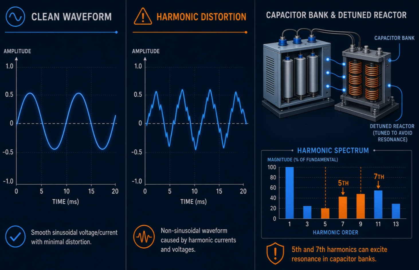
Capacitors reduce reactive power demand and improve power factor. However, capacitors also change the electrical characteristics of the network. In a harmonic-rich system, a capacitor bank can interact with transformer and network inductance, creating resonance at or near a dominant harmonic frequency.
When resonance occurs, harmonic voltage or current can be amplified. This may lead to excessive capacitor current, overheating, blown fuses, damaged contactors, nuisance tripping, and shortened equipment life.
For this reason, capacitor selection should never be based only on kvar demand. Engineers should evaluate harmonic measurements, system impedance, transformer capacity, existing compensation, load growth plans, and the dominant harmonic spectrum.
The proper solution depends on the site data. Typical options include:
| Site Condition | Potential Solution Direction |
|---|---|
| Low power factor with low harmonic distortion | Automatic capacitor bank or fixed compensation |
| Capacitor failures with moderate harmonics | Detuned reactor capacitor bank |
| High harmonic current from a defined load | Passive harmonic filter designed for the measured spectrum |
| Variable harmonic conditions or multiple nonlinear loads | Active harmonic filter |
| Simultaneous reactive power and harmonic issues | Hybrid system combining capacitors, reactors, and active filtering |
| Phase unbalance and reactive power fluctuation | Dynamic reactive power compensation or targeted load balancing strategy |
A high-quality solution should be based on measurement evidence, not on a standard cabinet configuration. At DINGNUO ELECTRIC, this principle guides the selection of reactive power compensation and harmonic-control equipment for different industrial operating environments.
Power quality standards serve different purposes. Understanding the distinction helps avoid incorrect comparisons.
EN 50160 describes the main voltage characteristics expected at the supply terminals of users connected to public AC electricity networks under normal operating conditions. It covers such characteristics as frequency, voltage magnitude, waveform, and voltage symmetry. The current EN 50160:2022 edition applies across low-, medium-, high-, and extra-high-voltage public networks and references EN 61000-4-30 measurement methods.
IEC 61000-4-30 focuses on how power quality parameters should be measured and interpreted. It supports repeatable measurement processes for in-situ assessments rather than prescribing a universal corrective design for every facility.
IEEE 519 provides recommended practices and requirements for harmonic control in electrical power systems. It is particularly relevant for evaluating harmonic distortion at the PCC and for coordinating the responsibilities of utilities and end users.
These standards should be applied with engineering judgment. A measurement result should be interpreted according to the installation, voltage level, applicable agreement, local requirements, system conditions, and the measurement location.
Consider a manufacturing facility that installs several variable-frequency drives to improve motor control and energy efficiency. Soon afterward, its monthly utility bill includes reactive-power charges, and the existing capacitor bank begins to experience repeated fuse failures.
A rushed response might be to add more capacitors. That can make the problem worse.
A better process is:
1. Measure power quality at the main incomer, capacitor bank, and major VFD feeders.
2. Record power factor, reactive power, current THD, voltage THD, and individual harmonic orders during normal and peak production.
3. Check whether capacitor current is excessive or whether a dominant harmonic frequency aligns with a possible resonance point.
4. Evaluate the transformer, cable system, existing capacitors, and load profile.
5. Select a detuned capacitor-reactor system, passive filter, active harmonic filter, or hybrid solution based on the data.
6. Re-measure after commissioning to verify improvement.
This approach converts power quality measurement from a troubleshooting activity into a repeatable improvement cycle: measure, diagnose, correct, verify, and maintain.
DINGNUO ELECTRIC CO., Ltd. is a professional manufacturer of capacitors and reactors focused on high-quality reactive power compensation and harmonic-control solutions. We help customers address power quality issues in industrial and municipal applications through product technology, engineering support, and application-oriented service.
Our solutions are suitable for projects involving:
- Reactive power compensation
- Power factor improvement
- Detuned capacitor banks
- Harmonic mitigation
- Capacitor and reactor selection
- Low-voltage distribution optimization
- Industrial load expansion
- Power quality troubleshooting
- Energy-efficiency improvement initiatives
For complex operating conditions—such as high temperatures, dust, frequent load fluctuations, heavy nonlinear loads, or sensitive automation systems—the right equipment configuration matters as much as the component quality.

Need a power quality solution designed around your actual load conditions? Contact DINGNUO ELECTRIC with your single-line diagram, transformer details, load list, existing compensation information, and any available power quality report. Our team can help evaluate the data and recommend an appropriate capacitor, reactor, or harmonic-control configuration for your project.
Power quality measurement identifies electrical conditions that can reduce efficiency, damage equipment, cause nuisance tripping, shorten capacitor life, or create production interruptions. It provides the data required to diagnose voltage, harmonic, reactive power, and imbalance problems before selecting a corrective solution.
The measurement duration should cover the actual operating cycle of the facility. A few hours may be enough for a specific event investigation, but several days or a full week is often more appropriate for industrial facilities with changing shifts, batch production, or variable loads.
Voltage THD measures distortion in the voltage waveform at a measurement point. Current THD measures distortion in the current drawn by loads. Nonlinear loads commonly produce distorted current, which can then create voltage distortion depending on the impedance of the electrical system.
Capacitors have low impedance at higher frequencies, which means they can attract harmonic current. If the capacitor bank interacts with system inductance at a resonant frequency, harmonic current and voltage may be amplified. This can cause overheating, fuse operation, dielectric stress, and premature failure.
A reactor may be necessary when the system contains meaningful harmonic distortion or nonlinear loads. Detuned reactors help prevent harmful resonance between capacitors and the electrical network. The correct reactor rating should be selected from measured data and system analysis, not from guesswork.
Not always. Power factor correction and harmonic mitigation are related but different objectives. A capacitor bank can improve reactive power performance, while harmonic control may require detuned reactors, passive filters, active harmonic filters, or a hybrid solution.
The best measurement point depends on the investigation. The PCC is important for utility-interface assessment, the main incomer provides a facility-wide view, capacitor-bank measurement checks compensation performance, and feeder-level measurement identifies individual harmonic-producing loads.
A useful report should include the measurement location, wiring configuration, instrument details, CT and VT ratios, logging period, voltage and current trends, power and power factor trends, harmonic spectrum, THD data, voltage events, phase unbalance, load observations, root-cause analysis, and recommended corrective actions.
1. International Electrotechnical Commission. IEC 61000-4-30:2025—Electromagnetic Compatibility (EMC), Part 4-30: Testing and Measurement Techniques—Power Quality Measurement Methods. Available at: [IEC Webstore]. [webstore.iec]
2. International Electrotechnical Commission. IEC 61000-4-30:2015+AMD1:2021 CSV—Power Quality Measurement Methods. Available at: [IEC Webstore]. [webstore.iec]
3. IEEE Standards Association. IEEE 519-2022—Recommended Practices and Requirements for Harmonic Control in Electrical Power Systems. Available at: [IEEE Standards Association]. [standards.ieee]
4. European Committee for Electrotechnical Standardization. EN 50160:2022—Voltage Characteristics of Electricity Supplied by Public Electricity Networks. Available at: [iTeh Standards Store]. [standards.iteh]
5. Fluke. What Does the IEC 61000-4-30 Class A Standard Mean to Me? Available at: [Fluke]. [fluke]
6. Hioki. What Is IEC 61000-4-30 Standard? Available at: [Hioki FAQ]. [hioki]
7. YT Electric. What Is the Power Quality Measurement? Available at: [YT Electric Blog]. [ytelect]


