
Views: 288 Author: Dingnuo Electric Publish Time: 2026-07-21 Origin: Site


Content Menu
● Active, Reactive and Apparent Power – A Practical Overview
● How Reactive Power Is Generated
>> Phase Shift Between Voltage and Current
>> Inductive Sources of Reactive Power
>> Capacitive Sources of Reactive Power
● Why Reactive Power Matters for Industrial Facilities
● Common Industrial Sources of Reactive Power
>> Motors and Variable‑Speed Drives
>> Transformers, Reactors and Distribution Networks
>> Capacitor Banks and Power Electronics
● Reactive Power Compensation – From Traditional Capacitors to Advanced Systems
>> Conventional Capacitor Bank Solutions
>> Advanced Static Var Systems
● Trends in Reactive Power and Power Quality Solutions
● Expert‑Level Steps to Improve Power Quality
● Integrated Power Quality Solutions with Capacitors and Reactors
● Enhancing Readability and Visual Understanding
● FAQs About Reactive Power and Power Quality
>> Q1: What is the main difference between active power and reactive power?
>> Q2: Why is reactive power important in industrial facilities?
>> Q3: Are traditional capacitor banks still useful today?
>> Q4: How do harmonics interact with reactive power compensation?
>> Q5: Which industries most need advanced reactive power solutions?
Reactive power is generated whenever AC systems use inductive or capacitive equipment that build up and release electric and magnetic fields, causing current and voltage to shift out of phase and creating non‑working "reactive" energy in the grid. For industrial plants, this reactive power must be carefully controlled and compensated to keep power factor high, electrical losses low, and sensitive equipment running reliably.
Reactive power is a core concept in modern power systems, especially in facilities that rely heavily on large motors, transformers, and power electronics. Although it does not perform direct mechanical work, it is indispensable for creating and sustaining the electric and magnetic fields that make AC equipment operate.
Understanding how reactive power is generated—and how to manage it effectively—is critical for any plant that aims to reduce energy costs, increase equipment lifetime, and maintain a stable, high‑quality power supply across complex production lines.
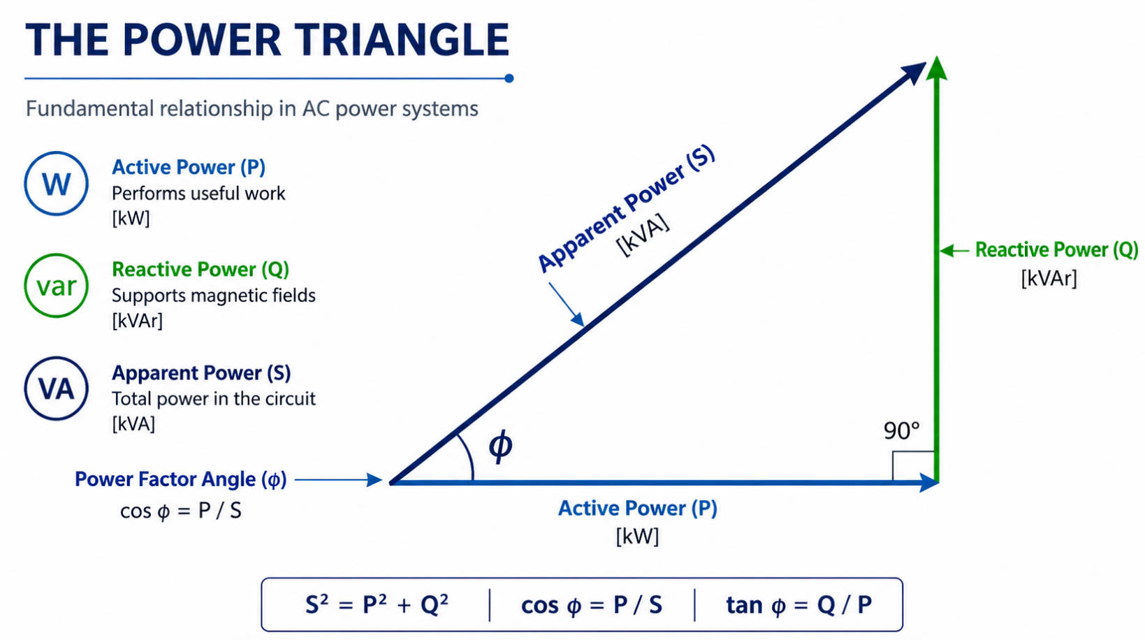
In any sinusoidal AC circuit, electrical power can be broken down into three components: active power, reactive power, and apparent power. Active power is the portion that performs useful work, such as driving motors, heating elements, or lighting systems. Reactive power is the part that flows back and forth between the source and field‑forming components, while apparent power represents the combined effect of both.
From a practical standpoint:
- Active power (P) is the "useful" power that directly supports production.
- Reactive power (Q) is the "supporting" power that sustains fields in inductors and capacitors.
- Apparent power (S) is the total power that the grid and plant infrastructure must carry.
Engineers often visualize these three components as a right‑triangle, where apparent power is the hypotenuse and active and reactive power are the two perpendicular sides. The angle of this triangle is directly related to the power factor, which quantifies how efficiently the electrical system is using the supplied power.
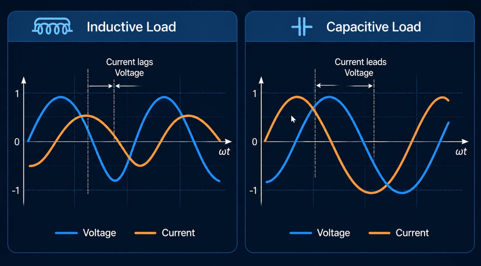
Reactive power fundamentally comes from phase differences between voltage and current. In a purely resistive circuit, voltage and current are in phase, and all supplied power is converted into useful work. However, once inductive or capacitive elements are introduced, voltage and current shift relative to each other.
- In inductive loads (motors, transformers, reactors), current lags voltage.
- In capacitive loads (capacitor banks, certain electronic devices), current leads voltage.
Because of this phase shift, there are portions of the AC cycle where instantaneous power becomes negative. This indicates that energy is being returned to the source rather than consumed, which is the essence of reactive power.
The most common generators of reactive power in industrial environments are inductive devices. These include:
- Induction motors driving pumps, fans, compressors and conveyors.
- Power transformers feeding distribution networks and large process equipment.
- Reactors used for voltage control, filtering and compensation.
In each of these devices, energy is stored in a magnetic field during part of the AC cycle and released back to the network during another part. This cyclical exchange does not contribute to net mechanical output but increases current flow and influences voltage stability.
Capacitive devices generate reactive power by storing energy in electric fields between their plates. In industrial plants, the most common intentional sources of capacitive reactive power are:
- Fixed capacitor banks installed on key feeders or busbars.
- Automatically switched capacitor banks that respond to changing loads.
- Power factor correction modules integrated in certain equipment.
These devices are often used deliberately to offset the reactive demand of inductive loads, thereby improving overall power factor and stabilizing voltage. However, uncontrolled or poorly coordinated capacitive compensation can lead to overcompensation or resonance issues.
In high‑load environments such as metallurgy, petrochemical, automotive, paper, textile and building materials, reactive power has a visible impact on performance and operating costs. Large motors, furnaces, and complex process equipment all consume reactive power to maintain their fields, and this demand can rise and fall quickly.
Several key issues arise when reactive power is not managed properly:
- Higher currents in cables and transformers, causing additional losses and heating.
- Voltage drops and instability, which can lead to nuisance trips and process interruptions.
- Reduced equipment lifetime, due to thermal stress and inefficient operating conditions.
- Increased cost of electricity, as the system must supply more apparent power for the same active power.
In many countries and regions, utilities and grid operators set limits on power factor and reactive power exchange. Plants that consistently draw large amounts of reactive power without adequate compensation often face penalties or stricter connection conditions.
Induction motors are among the largest consumers of reactive power in industrial sites. They are found across almost every sector, from rolling mills and extruders to pumps, compressors and fans. When combined with variable‑speed drives and other power electronic controllers, their reactive demand can become dynamic, changing rapidly as process conditions vary.
This dynamic behavior makes reactive power control more complex, as compensation must follow the load rather than simply address a fixed baseline.
Medium‑ and high‑voltage transformers that feed entire production units or plants contribute a permanent reactive background due to their magnetizing current. Reactors used in substation or plant‑level voltage regulation also consume reactive power as part of their normal operation.
In plants with extensive internal distribution networks, the combined effect of these devices can significantly influence voltage profiles and overall power factor, even before process loads are considered.
Capacitor banks and certain power electronic devices generate reactive power, usually intentionally. Traditional fixed capacitor banks provide stepwise capacitive support, while automatic banks switch stages in response to measured power factor.
Modern power electronic equipment can also generate or absorb reactive power on demand. This capability allows more precise control but must be coordinated with existing compensation hardware to avoid conflicts or overcompensation.
For decades, the primary solution to reactive power problems in industrial plants has been the installation of capacitor banks. These banks can be:
- Fixed, providing constant capacitive support.
- Automatically switched, adding or removing stages according to measured power factor and load conditions.
Conventional solutions are effective for relatively stable loads and can significantly improve power factor and voltage profiles. However, they have limitations when loads fluctuate quickly, when harmonics are present, or when multiple compensation devices interact.
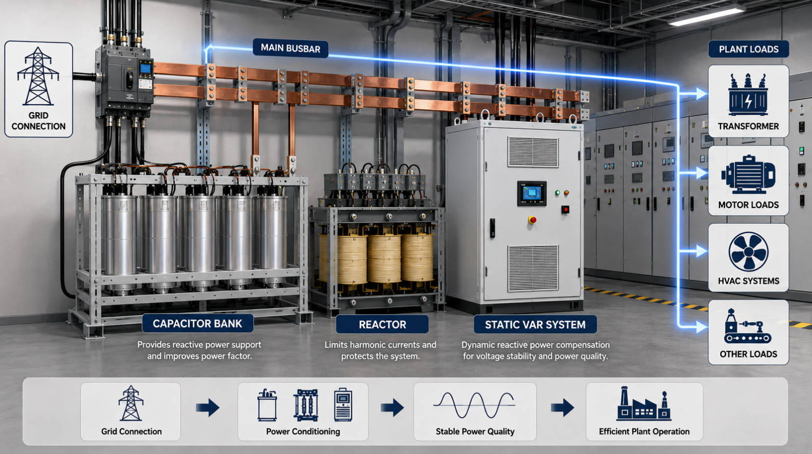
To address the limitations of static capacitor banks, many plants have adopted active systems such as static var generators or similar devices. These systems use power electronic converters and real‑time measurement to provide:
- Continuous, fast and bidirectional reactive power control.
- Dynamic compensation that follows load changes and process cycles.
- Concurrent harmonic mitigation and phase balancing, improving power quality on several fronts.
By reacting almost instantaneously to changes in load and voltage, advanced systems provide more accurate compensation, reduce the risk of overcompensation, and support higher levels of operational stability, especially in plants with complex or sensitive equipment.
Industrial and infrastructure operators are increasingly treating reactive power management as part of a broader power quality strategy. Several trends are shaping this evolution:
- Growing integration of renewables and power electronics, which changes the behavior of grids and internal networks.
- More stringent grid connection requirements, focusing on power factor, voltage support and harmonic emission.
- Wider use of digital monitoring and analytics, enabling continuous optimization instead of periodic adjustments.
Modern compensation systems often combine reactive power control with harmonic filtering, voltage stabilization and digital monitoring. This integrated approach turns power quality management into a strategic lever for reliability, energy efficiency and long‑term asset performance.
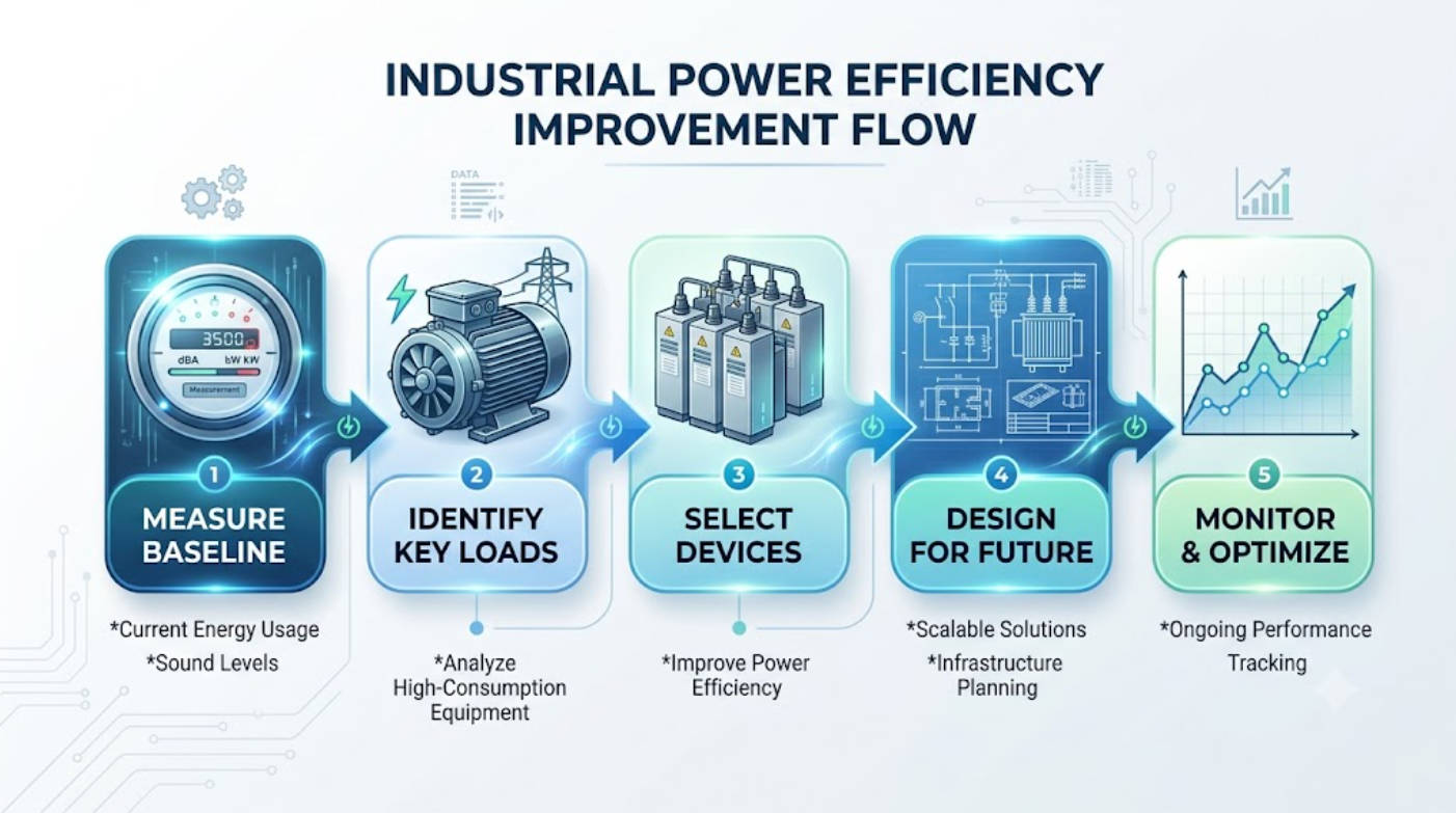
Industrial engineers can follow a structured process to diagnose and improve reactive power behavior in their facilities. A practical framework includes the following steps:
1. Measure baseline conditions
Begin by collecting detailed measurements of power factor, active and reactive demand, voltage profiles and harmonic distortion at critical points in the plant. This provides a clear picture of when and where problems occur.
2. Identify key loads and patterns
Map major inductive consumers, fluctuating process loads, and non‑linear devices that contribute harmonics. Pay particular attention to large motors, variable‑speed drives, furnaces and specialized process equipment.
3. Select the right combination of devices
Combine fixed capacitors, automatically switched banks and advanced static var systems according to the behavior of different loads. Ensure that these devices are correctly coordinated with protection systems and that resonance risks are addressed.
4. Design for future evolution
Include headroom for planned and potential load growth. Consider future regulatory requirements and possible technology changes, such as increased use of power electronics or new process lines.
5. Monitor and continuously optimize
Use metering and data‑logging tools to track performance over time. Adjust settings, stage sizes and device configurations as production patterns evolve, ensuring that compensation remains effective and stable.
By handling reactive power in this systematic way, plants can move from reactive fixes to proactive design, reducing the total cost of ownership for electrical infrastructure while improving process reliability.
Companies that specialize in capacitors and reactors for reactive power compensation and harmonic control provide a complete set of tools for addressing power quality challenges. Their products and solutions can be configured to meet the specific needs of different sectors, from heavy industry to municipal projects.
Such solutions are widely deployed in:
- Metallurgy and metal processing, where large furnaces and motor drives dominate.
- Petrochemical and chemical plants, with extensive rotating equipment and complex process lines.
- Automotive, paper and textile production, where production lines change over time and require flexible, modular systems.
- Building materials and municipal infrastructure, where voltage stability and compliance with grid requirements are paramount.
By combining capacitors, reactors and advanced control equipment, these solutions help improve voltage profiles, optimize power factor, reduce harmonic distortion and extend the lifetime of motors, cables and transformers.
Reactive power is an abstract concept, but it becomes much easier to understand with clear visuals and structured explanations. To support different audiences—engineers, technicians and managers alike—the following visual elements are particularly effective:
- A diagram of the power triangle, showing the relationship between active, reactive and apparent power.
- Waveform illustrations highlighting voltage–current phase shifts for inductive and capacitive loads.
- Schematic layouts of capacitor banks, reactors and static var systems installed in typical industrial environments.
- A flow chart summarizing the step‑by‑step improvement process for power quality assessment and compensation design.
Combined with short paragraphs, bold highlighting of key terms and carefully designed lists, these visuals make complex power concepts more approachable and actionable.
Reactive power is generated whenever inductive and capacitive devices create and release electric and magnetic fields, resulting in phase shifts between voltage and current. Although this power does not deliver direct mechanical output, it is vital for the operation of motors, transformers, capacitors and modern power electronics.
In industrial environments, uncontrolled reactive power leads to higher losses, voltage instability and increased stress on equipment. Through a combination of precise measurement, carefully selected capacitor and reactor configurations, and advanced static var systems, plants can transform reactive power from a hidden cost driver into a manageable design parameter that supports both reliability and efficiency.
Active power is the component of electrical power that performs work, such as driving motors or heating elements, while reactive power sustains electric and magnetic fields without being converted into mechanical output or heat.
Reactive power is essential for operating inductive and capacitive equipment, but when it is not properly managed it increases currents, causes voltage instability and may shorten equipment lifetime, especially in plants with large motors and complex process loads.
Traditional fixed and automatically switched capacitor banks remain effective for many applications, particularly where loads are relatively stable. However, they are often complemented by advanced static var systems in plants with highly dynamic or sensitive loads.
Harmonics arise from non‑linear loads and distort voltage and current waveforms. This can complicate reactive power behavior and, in some cases, create resonance issues. Modern compensation systems frequently include harmonic filtering to ensure stable and safe operation.
Industries with large rotating machinery, complex process equipment and strict grid requirements—such as metallurgy, petrochemical, automotive, paper, textile, building materials and municipal infrastructure—derive significant benefits from advanced reactive power and power quality solutions.
Article summary (meta description, ≈300 characters):
Reactive power is essential for AC equipment yet costly when unmanaged. This in‑depth guide explains how reactive power is generated, why it matters for industrial plants, and how modern capacitor, reactor and static var solutions enhance power quality and operational reliability.


