
Views: 259 Author: Dingnuo Electric Publish Time: 2026-08-13 Origin: Site


Content Menu
● Why Low Power Factor Increases Electrical Costs
>> 1. Reactive Power Charges and Power Factor Penalties
>> 2. Higher Current and Higher Cable Losses
>> 3. Reduced Transformer Capacity
>> 4. Increased Demand Charges
● Which Equipment Causes Low Power Factor?
● What Is a Good Power Factor for Industrial Facilities?
● Why Capacitor Banks Are Not Always Enough
● When Should You Use a Detuned Reactor Capacitor Bank?
● Capacitor Bank, SVG, or Active Harmonic Filter?
>> SVG Systems
● How to Calculate Required Power Factor Correction Capacity
● A Five-Step Process for Improving Industrial Power Factor
>> 1. Review Your Electricity Bills
>> 2. Measure Power Quality Under Real Conditions
>> 3. Identify the Main Source of Reactive Power Demand
>> 4. Select the Right Compensation Technology
>> 5. Commission and Maintain the System
● Power Factor Correction Across Industrial Applications
>> Metallurgy
>> Paper and Textile Manufacturing
● Choose a Complete Power Quality Solution
>> 1. Does low power factor always increase electricity bills?
>> 2. What power factor should an industrial facility maintain?
>> 3. Can a capacitor bank eliminate harmonics?
>> 4. What is the difference between a capacitor bank and an SVG?
>> 5.How do I know whether I need a detuned reactor?
>> 6. Can power factor correction increase transformer capacity?
>> 7. How often should a power factor correction system be maintained?
For many industrial facilities, power factor becomes a concern only after electricity costs increase, transformer capacity becomes limited, or capacitor banks begin to fail. In reality, power factor correction is not only about avoiding utility penalties. It is also a practical way to reduce unnecessary current, improve available electrical capacity, and support more stable power quality.
For factories, infrastructure projects, and high-load commercial facilities, low power factor can affect electricity billing, cable losses, transformer loading, voltage stability, and future expansion plans. The right solution depends on the facility's real load profile, utility tariff, harmonic environment, and operational requirements.
DINGNUO ELECTRIC CO., Ltd. provides reactive power compensation and harmonic control solutions for industrial users worldwide. Our capacitor banks, reactors, SVG systems, active harmonic filters, and integrated power quality solutions are widely applied in metallurgy, petrochemical processing, automotive manufacturing, paper production, textiles, building materials, and major municipal engineering projects.
This guide explains what power factor really affects, why it matters to industrial electricity users, and how to choose a suitable power factor correction solution.
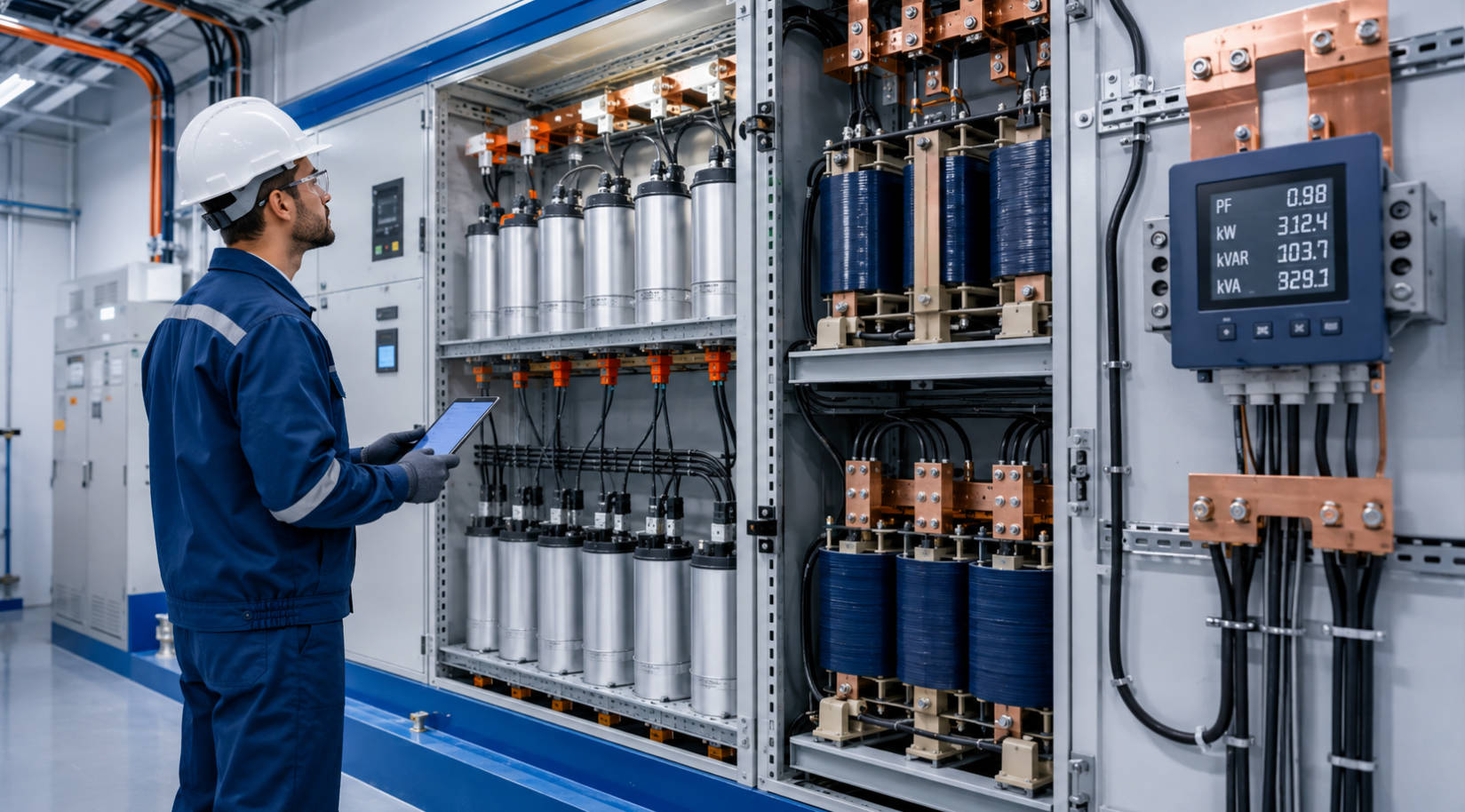
Power factor measures how effectively an electrical system converts supplied power into useful work.
It is expressed as:
Power Factor=Active Power (kW)/Apparent Power (kVA)
A power factor close to 1.00 means the facility is using supplied electrical capacity efficiently. A lower power factor means the system must draw more current and more apparent power to deliver the same useful active power.
In an industrial electrical system, three power values are important:
| Electrical term | Unit | Meaning |
|---|---|---|
| Active power | kW | Power that performs useful work, such as driving motors, operating machinery, producing heat, or moving materials |
| Reactive power | kVAR | Power required to establish magnetic fields in motors, transformers, inductors, and other inductive loads |
| Apparent power | kVA | Total power capacity required from the utility, transformer, cables, busbars, and switchgear |
Reactive power is not "wasted" power. Motors, transformers, pumps, compressors, fans, and other inductive equipment need it to operate. However, when reactive power is not properly managed, the facility draws more current than necessary from the electrical network.
That additional current creates financial and technical consequences.
The exact effect of low power factor on an electricity bill varies by country, utility, tariff, and supply contract. Some users are billed primarily in kWh, while others may also pay according to maximum kW demand, kVA demand, kVAR demand, or kVARh consumption.
However, low power factor commonly affects industrial users in four important ways.
Many utilities set a minimum power factor requirement for industrial and commercial customers. If a site operates below the required threshold, the utility may apply:
- Reactive energy charges based on kVARh
- Reactive demand charges based on kVAR
- Power factor penalties
- Higher billed kVA demand
- Adjusted demand charges
- Additional monthly surcharges
For example, some utility billing structures charge for reactive energy above a defined percentage of active energy consumption. Other utilities calculate penalties when the average power factor falls below a specified target.
The target is not the same everywhere. It may be 0.90, 0.95, 0.98, or another value defined by the local electricity supplier.
Important: Do not assume a fixed saving from power factor correction. The potential financial benefit must be calculated from your own electricity bills, tariff structure, operating hours, demand profile, and reactive power charges.
When active power remains the same but power factor decreases, current increases.
For a three-phase system:
P = sqrt{3}×V×I×PF
If voltage and active power remain constant, a lower power factor requires higher current.
Higher current can cause:
- Increased cable and busbar losses
- More heat in transformers and switchgear
- Higher voltage drop across the distribution system
- Greater stress on electrical connections
- Higher internal energy losses
- Reduced usable capacity of existing infrastructure
These losses are often not shown as a separate line on the utility bill. Instead, they appear as higher internal consumption, overheating, equipment derating, or reduced system reliability.
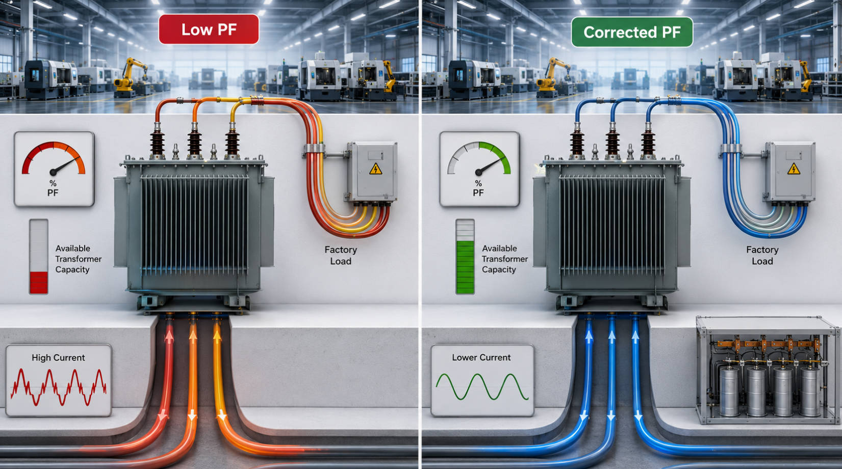
Transformers are rated in kVA, not kW. A low power factor uses transformer capacity that could otherwise be used for productive equipment.
Consider a 1,600 kVA transformer.
| Operating power factor | Available active power |
|---|---|
| 0.80 | 1,280 kW |
| 0.85 | 1,360 kW |
| 0.90 | 1,440 kW |
| 0.95 | 1,520 kW |
At 0.80 power factor, the transformer can support approximately 1,280 kW of useful active load. At 0.95 power factor, the same transformer can support approximately 1,520 kW.
This difference can be important when a facility wants to:
- Add a new production line
- Install more motors or pumps
- Expand a workshop
- Upgrade automation equipment
- Add HVAC or compressed-air systems
- Avoid purchasing a larger transformer
Facilities billed on kVA demand may pay more when their power factor is low. The same useful kW load requires more apparent power from the utility.
For example, assume a plant needs 1,000 kW of active power.
At 0.80 power factor:
kVA=1,000/0.80=1,250 kVA
At 0.95 power factor:
kVA=1,000/0.95≈1,053 kVA
The plant still needs 1,000 kW of useful power. But after correction, it requires approximately 197 kVA less apparent power.
If the utility tariff includes kVA-based demand billing, this reduction may lower demand-related costs. It can also release capacity in transformers, generators, switchgear, and distribution feeders.
Low power factor is common in facilities with large inductive loads. The most common sources include:
- Induction motors
- Pumps and compressors
- Fans and blowers
- Transformers
- Welding equipment
- Conveyor systems
- Cranes and hoists
- Conventional fluorescent lighting
- Induction heating equipment
- Machine tools
- Air-conditioning systems
- Refrigeration equipment
Motors operating at light load are a particularly common cause. An oversized motor can draw magnetizing current even when it is not delivering its rated mechanical output.
However, low power factor should not automatically be blamed on motors alone. A professional assessment should measure the complete electrical system and identify where reactive power demand is created.
There is no single "perfect" power factor for every factory.
Many industrial facilities aim for a power factor between 0.95 and 0.99. However, the correct target should be based on:
- Utility billing requirements
- Local grid regulations
- Transformer capacity
- Production operating patterns
- Seasonal load changes
- Harmonic conditions
- Existing compensation equipment
- Risk of overcompensation
A facility should not blindly target 1.00 power factor at all times. Overcompensation can cause a leading power factor, voltage rise, switching instability, and unnecessary stress on electrical equipment.
The practical goal is to maintain a stable power factor within an efficient and utility-compliant range.
Capacitor banks are widely used for power factor correction because they supply reactive power locally. This reduces the reactive power that must be supplied by the utility network.
A conventional capacitor bank may be an effective solution for stable motor loads in a clean electrical network. However, modern factories often contain nonlinear loads that create harmonics.
Common harmonic-producing equipment includes:
- Variable frequency drives
- Servo drives
- Rectifiers
- UPS systems
- Welding machines
- CNC equipment
- Induction furnaces
- Battery chargers
- LED drivers
- Data center power supplies
In harmonic-rich environments, installing a standard capacitor bank without analysis can create problems.
Potential risks include:
- Capacitor overheating
- Capacitor fuse failures
- Bulging capacitor cases
- Reactor overheating
- Frequent controller alarms
- Breaker tripping
- Transformer temperature rise
- Voltage distortion
- Harmonic resonance
- Shortened equipment life
Capacitors can interact with the inductance of transformers, cables, and the utility network. If the system resonance frequency is close to a dominant harmonic frequency, harmonic current may be amplified.
This is why a basic capacitor bank should not be selected only by kVAR rating.
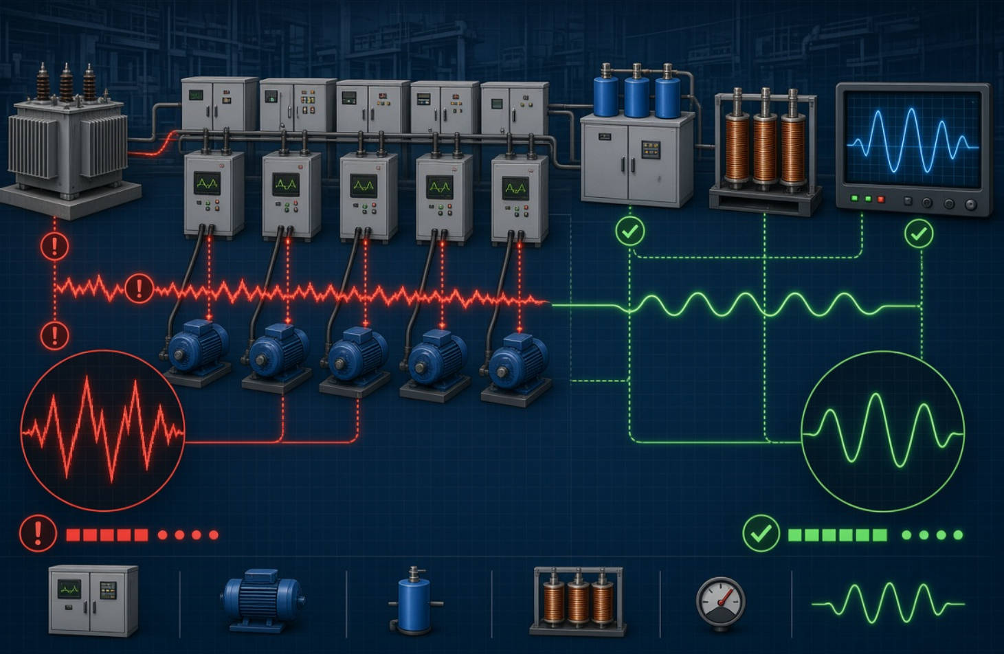
A detuned reactor capacitor bank is designed for systems with harmonic-producing loads. The reactor is connected in series with the capacitor stage to shift the resonant frequency away from dominant harmonics.
This helps protect the capacitor bank and reduces the risk of harmonic amplification.
A detuned capacitor bank may be suitable for facilities with:
- VFD-driven pumps and fans
- Automated production lines
- CNC machinery
- Rectifier systems
- Textile machinery
- Plastic extrusion equipment
- Welding workshops
- UPS systems
- Commercial buildings with large nonlinear loads
- Manufacturing plants with mixed motor and drive loads
The exact detuning ratio must be selected based on measured electrical data. Important factors include transformer impedance, short-circuit capacity, harmonic spectrum, capacitor voltage rating, existing loads, and future expansion plans.
A reliable design begins with a power quality measurement—not with an assumed standard configuration.
Different electrical systems require different correction technologies.
| Facility condition | Recommended solution | Main benefit |
|---|---|---|
| Stable motor load and low harmonic distortion | Fixed capacitor bank | Economical basic reactive power compensation |
| Load varies by shift or production process | Automatic capacitor bank | Switches capacitor stages according to demand |
| Network has VFDs, rectifiers, or harmonic distortion | Detuned reactor capacitor bank | Reduces resonance risk and protects capacitors |
| Reactive load changes rapidly | SVG | Fast and stepless reactive power compensation |
| Harmonics, reactive power, and unbalance occur together | Active harmonic filter | Improves overall power quality |
| Heavy and fluctuating industrial load | Hybrid solution | Combines capacitors, reactors, SVG, and filtering technologies |
Fixed capacitor banks are suitable for loads that remain relatively stable. They are often used for continuously operating motors, pumps, fans, and transformers.
They are cost-effective but may not perform well where loads change frequently. If the load drops significantly, the system may become overcompensated.
Automatic capacitor banks use a power factor controller to switch capacitor stages in and out according to system demand.
They are suitable for facilities where the load changes throughout the day, such as factories with multiple production lines, compressors, pumping systems, and motor groups.
The step size is important. Very large capacitor steps may cause unstable correction. Very small steps may increase switching frequency and equipment wear.
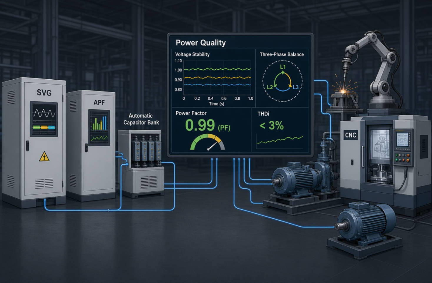
A Static Var Generator, or SVG, provides fast and continuous reactive power compensation.
Unlike conventional capacitor banks, an SVG does not compensate in fixed steps. It dynamically injects or absorbs reactive power according to load changes.
SVG systems are often suitable for:
- Metallurgical production
- Arc furnaces
- Welding-intensive workshops
- Automotive manufacturing
- Fast-changing motor loads
- Paper machines
- Textile equipment
- Cranes and lifting systems
- Municipal pumping stations
- Ports and logistics facilities
SVG technology can support voltage stability and help manage unbalanced reactive power, depending on the system design.
An active harmonic filter is used where harmonic distortion is a major issue. It can inject compensating current to reduce harmonic currents in the network.
Active harmonic filters may be appropriate where facilities experience:
- High total harmonic distortion
- Transformer overheating
- Neutral conductor overheating
- Frequent tripping
- Sensitive control system faults
- Harmonic-related capacitor failures
- Poor power quality caused by nonlinear loads
For demanding applications, a hybrid solution may combine detuned capacitor banks, SVG systems, and active harmonic filters.
A common preliminary formula for capacitor bank sizing is:
Qc=P(tanφ1−tanφ2)
Where:
Qc is the required capacitor capacity in kVAR
P is active power in kW
φ1 is the existing power factor angle
φ2 is the target power factor angle
For example, if a facility has a 500 kW load and wants to improve power factor from 0.80 to 0.95, the required compensation can be estimated using the power factor correction formula.
However, this is only a starting point.
Final equipment sizing should also consider:
- Minimum and maximum operating load
- Load diversity
- Future expansion
- Harmonic distortion
- Transformer capacity
- Voltage level
- Switching frequency
- Required response speed
- Utility requirements
- Installation location
- Ambient temperature
- Ventilation conditions
A properly designed solution should improve performance under actual operating conditions, not only under one theoretical load point.
Collect at least 12 months of utility bills and identify:
- Active energy consumption in kWh
- Maximum demand in kW or kVA
- Reactive energy consumption in kVARh
- Reactive demand charges
- Power factor penalties
- Seasonal demand changes
- Peak production periods
- Contracted capacity
This step identifies whether poor power factor is creating a direct billing issue.
Use a professional power quality analyzer to measure:
- kW, kVAR, and kVA
- Power factor
- Current and voltage by phase
- Total harmonic distortion
- Individual harmonic orders
- Voltage unbalance
- Peak demand
- Load variation
- Switching events
Measurements should cover real operating conditions. A short test during low production may not represent the actual electrical profile of the facility.
Determine whether low power factor comes from:
- Lightly loaded motors
- Oversized motors
- Transformers operating at low load
- Pumps and fans
- Compressors
- Welding systems
- Inductive process equipment
- Poorly coordinated capacitor banks
- Harmonic distortion
The best solution addresses the cause, not only the visible power factor value.
Choose fixed capacitors, automatic capacitor banks, detuned reactors, SVG systems, active harmonic filters, or hybrid solutions according to the measured data.
Avoid selecting equipment based only on price or total kVAR capacity.
After installation, verify:
- Actual power factor improvement
- Utility billing performance
- Capacitor temperature
- Reactor temperature
- Harmonic levels
- Switching operation
- Absence of leading power factor
- Controller settings
- Transformer loading
Regular preventive maintenance helps protect the investment and maintain long-term power quality performance.
Metallurgical facilities may use large motors, furnaces, rolling equipment, rectifiers, and heavy-duty process loads. Reactive power demand and harmonics can vary rapidly.
A hybrid solution with SVG, detuned capacitor banks, and harmonic filtering may be required depending on the operating characteristics.
Petrochemical plants often operate pumps, compressors, fans, motors, and process equipment continuously. Reliability is essential, and the power factor solution must support stable operation while meeting strict safety and maintenance requirements.
Automotive plants often use robotic welding, conveyors, servo systems, machine tools, and automated production lines. These applications can create dynamic reactive power demand and harmonic distortion.
Fast-response SVG systems or hybrid compensation solutions may provide better performance than conventional capacitor banks alone.
Paper and textile facilities often use large numbers of motors, variable-speed drives, fans, pumps, and production machinery. Their load profile may change between production stages, shifts, and product types.
Automatic capacitor banks and detuned reactor systems are often evaluated for these applications.
Municipal water treatment plants, pumping stations, transport infrastructure, and public facilities may operate with varying motor loads. A reliable solution should consider remote monitoring, maintenance access, available installation space, and long-term operating stability.
Power factor correction is not simply a capacitor purchasing decision. It is an electrical system optimization project.
A successful solution should improve power factor while protecting the network from harmonic resonance, overcompensation, overheating, excessive switching, and avoidable equipment failures.
DINGNUO ELECTRIC CO., Ltd. provides comprehensive reactive power compensation and harmonic control products for industrial and infrastructure applications. Our solutions include capacitor banks, automatic power factor correction cabinets, detuned reactor systems, thyristor-switched capacitor banks, SVG systems, active harmonic filters, and integrated power quality solutions.
If your facility is experiencing power factor penalties, rising kVA demand, overloaded transformers, capacitor failures, harmonic alarms, or unstable voltage, the first step is a professional power quality assessment.
Contact DINGNUO ELECTRIC today to discuss your power factor correction, harmonic mitigation, and electrical power quality requirements. Our technical team can help evaluate your load profile and recommend a tailored solution for your facility.
Not always in the same way. The financial impact depends on the utility tariff, contract terms, billing method, reactive-power charges, and whether the facility is billed according to kW, kVA, kVAR, or kVARh.
Many industrial facilities target 0.95 or above, but the correct target depends on local utility rules, tariff requirements, load patterns, and electrical system conditions. Avoid overcompensation and leading power factor.
No. A conventional capacitor bank is designed mainly for reactive power compensation. In a harmonic-rich system, it may require detuned reactors, active harmonic filters, or a hybrid solution to avoid resonance and equipment damage.
A capacitor bank supplies reactive power in fixed or switched steps. An SVG provides fast, continuous, and stepless reactive power compensation. SVG systems are usually better suited to rapidly changing loads.
A detuned reactor should be considered if the facility has VFDs, rectifiers, UPS systems, welders, furnaces, servo drives, or other nonlinear loads. A harmonic measurement is needed before final selection.
Yes. Since transformers are rated in kVA, improving power factor allows more of that capacity to be used for useful active power in kW. This may delay or avoid the need for transformer upgrades.
Maintenance intervals depend on operating conditions, switching frequency, ambient temperature, harmonic levels, and equipment design. Regular thermal inspection, capacitor checks, controller verification, and power quality monitoring are recommended.
1. U.S. Department of Energy. Continuous Energy Improvement in Motor Driven Systems — explains active power, reactive power, apparent power, power factor, and examples of reactive-power billing structures. [Read the DOE guide].
2. U.S. Department of Energy. Understanding Your Electricity Bills — outlines power-factor-adjusted demand and how lower power factor increases apparent-power requirements. [Read the presentation].
3. U.S. Department of Energy. Reducing Power Factor Cost — discusses practical actions such as reducing lightly loaded motor operation and using capacitors to reduce reactive power demand. [Read the fact sheet].
4. IEEE Standards Association. IEEE Std 519-2022: Recommended Practice and Requirements for Harmonic Control in Electric Power Systems — provides harmonic-control design goals and addresses the point of common coupling. [View the standard overview].
5. U.S. Department of Energy. Electricity Distribution System Baseline Report — explains capacitor use, resonance risks, harmonic currents, heating, and potential equipment damage. [Read the report].
6. Schneider Electric. Power Factor Correction Capacitor Bank Installation and Operation Manual — describes how capacitor banks supply capacitive reactive current and reduce current drawn from the electrical supply. [Read the manual].


