
Views: 265 Author: Dingnuo Electric Publish Time: 2026-08-27 Origin: Site


Content Menu
● What Are Harmonics—and Why Do They Matter?
● The Key Harmonic Mitigation Techniques Compared
● Line Reactors and DC Chokes: First-Line Harmonic Reduction
>> When reactors are a good fit
● Detuned Capacitor Banks: Safer Power Factor Correction in Harmonic Networks
>> Why detuned reactors matter
>> Important distinction: detuning is not full filtering
● Passive Harmonic Filters: High-Capacity Filtering for Stable Loads
>> Where passive filters perform well
>> Passive filter design considerations
● Active Harmonic Filters: Dynamic Control for Modern Nonlinear Loads
>> When active harmonic filters are the better choice
>> Benefits of active filtering
● Hybrid Harmonic Filters: The Best Approach for Complex Industrial Sites
>> Why hybrid systems are increasingly used
● A Practical Harmonic Mitigation Selection Process
>> 1. Measure at the right locations
>> 2. Identify the dominant source and harmonic order
>> 3. Check for capacitor-bank resonance risk
>> 4. Define the performance target
>> 5. Select, validate, and monitor
● Expert Perspective: Avoid "Capacitor-Only" Decisions
● Improve Your Plant's Power Quality
● FAQ
>> 1. What is the difference between a detuned reactor and a harmonic filter?
>> 2. Can a capacitor bank reduce harmonics?
>> 3. When should I use an active harmonic filter?
>> 4. Are passive harmonic filters better than active harmonic filters?
>> 5. Where should harmonic distortion be measured?
>> 6. Why do capacitor banks fail in plants with VFDs?
>> 7. Is IEEE 519 a limit for every individual device?
Harmonic mitigation is no longer a niche concern in industrial electrical design. As variable-frequency drives (VFDs), rectifiers, welding equipment, UPS systems, arc furnaces, EV chargers, and other nonlinear loads become more common, harmonic distortion, capacitor overload, resonance, nuisance tripping, and overheating can quickly become costly reliability issues.
At DINGNUO ELECTRIC CO., Ltd., we work with industrial power-quality applications where reactive power compensation and harmonic control must operate together—not compete with one another. This guide compares the major harmonic mitigation techniques, explains where each solution works best, and provides a structured method for selecting capacitor banks, detuned reactors, passive harmonic filters, active harmonic filters, and hybrid systems.

Electrical harmonics are voltage or current components that occur at integer multiples of the fundamental supply frequency. In a 50 Hz system, the fifth harmonic is 250 Hz; in a 60 Hz system, it is 300 Hz.
Nonlinear loads do not draw current in a smooth sinusoidal waveform. Instead, they pull current in pulses. Those pulses distort the power system and can circulate through transformers, cables, capacitor banks, switchgear, and upstream utility networks.
Common industrial harmonic sources include:
- Variable-frequency drives and soft starters
- Six-pulse and twelve-pulse rectifiers
- UPS systems and data-center power supplies
- Arc furnaces and welding machines
- Induction heating equipment
- LED lighting drivers
- Solar inverters and EV charging systems
- CNC machinery and automated production lines
The consequences can be significant:
- Capacitor bank overheating and premature failure
- Transformer and cable losses
- Overloaded neutral conductors
- False operation of relays and protection devices
- Voltage distortion at sensitive loads
- Repeated breaker trips or fuse failures
- Reduced power-factor-correction performance
- Production interruptions and maintenance costs
- Difficulty meeting utility or project harmonic requirements
IEEE 519-2022 provides steady-state voltage and current distortion objectives at the point of common coupling (PCC), which is the interface between the user installation and the supplying power system. The standard emphasizes that compliance must be assessed at the PCC rather than simply at an individual drive, panel, or capacitor bank.
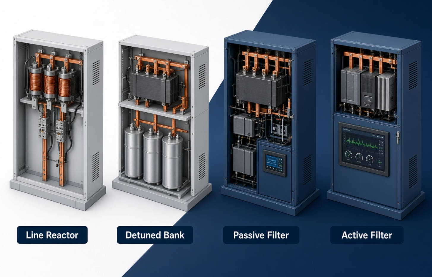
There is no universal "best harmonic filter." The correct choice depends on the load profile, harmonic spectrum, network impedance, short-circuit capacity, space, power-factor target, future expansion plans, and required performance at the PCC.
| Harmonic Mitigation Technique | Primary Function | Best Application | Key Advantage | Main Limitation |
|---|---|---|---|---|
| Line reactor / AC reactor | Reduces current distortion and limits inrush | Individual VFDs and small nonlinear loads | Simple, durable, economical | Limited filtering capability |
| DC choke | Smooths DC-link current in drives | VFD and rectifier applications | Compact solution inside drive systems | Does not solve plant-wide distortion |
| Detuned capacitor bank | Power-factor correction while avoiding resonance | Plants with moderate harmonic loads | Protects capacitor banks and improves PF | Does not actively cancel harmonics |
| Passive harmonic filter | Filters specific harmonic orders | Stable, predictable harmonic profiles | High-capacity and cost-effective | Can be affected by system changes |
| Active harmonic filter | Injects compensating harmonic current | Dynamic, mixed, changing nonlinear loads | Flexible and highly responsive | Higher initial cost |
| Hybrid harmonic filter | Combines passive and active filtering | Large facilities with heavy harmonic demand | Balances capacity and flexibility | Requires coordinated engineering |
| Multi-pulse rectifier / phase shifting | Reduces harmonics at the source | Large new installations | Lowers harmonic generation | Less practical for retrofit projects |
Line reactors and DC chokes are often the first mitigation measure considered for VFDs and rectifier-fed equipment. They add impedance to the circuit, helping reduce current distortion, limit inrush current, and protect sensitive components from voltage transients.
An AC line reactor is installed on the input side of the drive. A DC choke is typically installed in the DC link of a VFD.
Reactors are appropriate when:
- The facility has a limited number of drives
- Harmonic limits are not extremely strict
- The objective is to improve individual equipment performance
- Budget and installation space are limited
- The project requires basic harmonic reduction rather than full plant-level filtering
A reactor is not a complete harmonic solution for a heavily distorted industrial bus. It may reduce harmonic current produced by a specific drive, but it does not actively measure and cancel changing harmonic components throughout the distribution system.
For facilities with many VFDs, large rectifier loads, or existing capacitor banks, relying only on line reactors can leave the main issue unresolved: harmonic interaction across the entire electrical network.
A conventional capacitor bank is designed to improve power factor by supplying reactive power locally. However, when harmonic-producing loads are present, an ordinary capacitor bank can create or amplify resonance.
This is one of the most common and costly mistakes in industrial power-factor-correction projects: installing capacitors without first assessing the harmonic environment.
A detuned capacitor bank combines capacitors with series reactors. The reactor shifts the resonant frequency of the capacitor-reactor circuit below the lowest dominant harmonic frequency. This helps prevent the bank from attracting excessive harmonic current and reduces the risk of parallel resonance with the supply system.
ABB notes that a common approach to avoiding resonance is connecting an inductive reactance in series with the capacitor, with the resonance frequency designed below the lowest harmonic voltage present in the network.
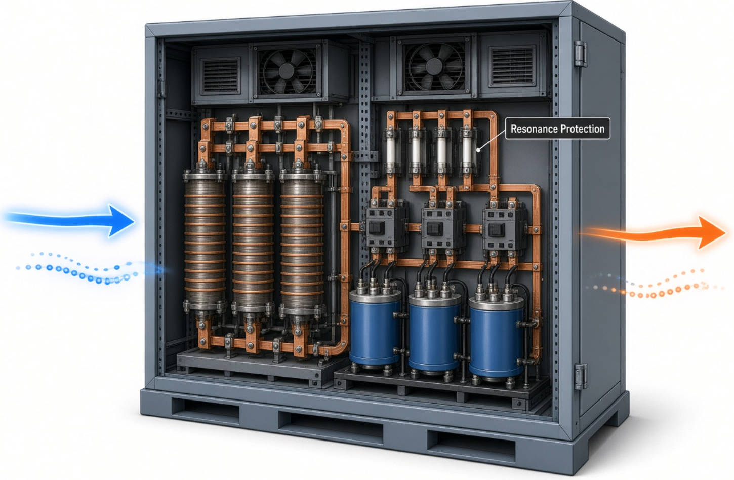
A properly designed detuned reactor can help:
- Protect capacitor banks from harmonic overload
- Reduce the risk of resonance amplification
- Extend capacitor service life
- Improve the reliability of automatic power-factor-correction panels
- Support stable reactive power compensation in industrial systems
Detuned capacitor banks are often misunderstood. Their main purpose is resonance avoidance and capacitor protection, not deep harmonic elimination.
For example, a 7% detuned reactor commonly shifts the capacitor bank resonance below the fifth harmonic in a 50 Hz system. This can make the capacitor bank safer in a system with significant fifth-harmonic content. However, it does not mean the system's fifth-harmonic current will be fully removed.
Choose detuned capacitor banks when the primary objective is safe power-factor correction in a harmonic environment. Choose tuned passive filters, active filters, or hybrid systems when the project also requires substantial harmonic reduction.
Passive harmonic filters use capacitors and reactors arranged in tuned circuits. Each filter branch is designed to provide a low-impedance path for a selected harmonic frequency, such as the fifth, seventh, eleventh, or thirteenth harmonic.
A passive filter can also provide reactive power, making it particularly useful in large industrial applications that need both power-factor correction and harmonic filtering.
Passive harmonic filters are often suitable for:
- Steel and metallurgy facilities
- Cement and building-material plants
- Petrochemical operations
- Pulp and paper mills
- Textile production lines
- Large pump and fan systems
- Centralized VFD installations
- Stable rectifier and converter loads
Passive filters can be highly effective where the dominant harmonic orders are known and relatively stable. Schneider Electric describes passive filters as reactor-capacitor circuits tuned to the harmonic frequency targeted for elimination, with multiple filters used where several harmonic orders must be addressed. [canada.newark]
A passive filter must be engineered around the real operating system—not selected only from a catalog.
Critical design inputs include:
- Transformer capacity and impedance
- System short-circuit level
- Existing capacitor banks and kvar requirements
- Load demand profile
- Harmonic spectrum by operating condition
- Voltage level and frequency
- Expected future expansion
- Required harmonic performance at the PCC
- Potential resonance points
A filter designed around inaccurate load data may perform poorly or create unexpected resonance conditions. This is why field measurement and engineering verification should come before final equipment sizing.
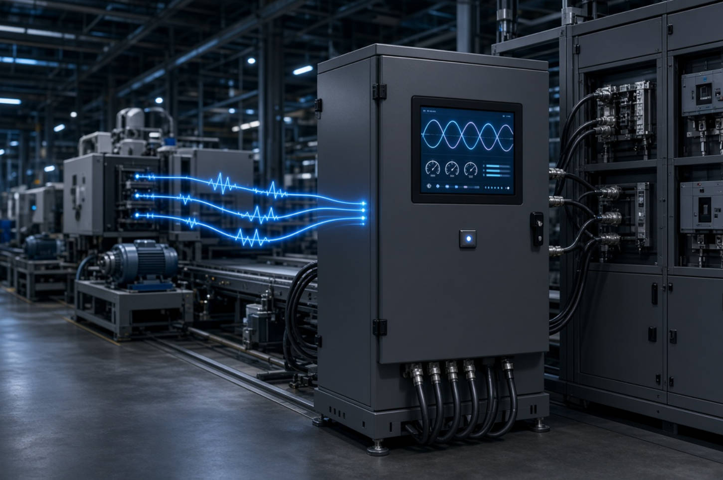
An active harmonic filter (AHF) continuously measures load current and injects an equal but opposite compensating current. This cancellation process reduces the harmonic current that would otherwise flow upstream into the electrical system.
Unlike a passive filter, an AHF does not need to be tuned only to one fixed harmonic order. It can respond to multiple harmonic orders and changing load conditions.
Active harmonic filters are especially valuable when loads are dynamic, diverse, or difficult to predict, such as:
- Production lines with frequently changing operating states
- Facilities with many different VFD ratings
- Automotive manufacturing plants
- Commercial and industrial EV charging sites
- Data centers and UPS-supported loads
- Electronics manufacturing
- Retrofit projects with limited shutdown windows
- Plants expecting future nonlinear-load expansion
- Targets multiple harmonic orders simultaneously
- Adapts to changing harmonic profiles
- Can compensate reactive power in many configurations
- Can help address phase imbalance, depending on the system design
- Enables modular expansion as load increases
- Avoids the narrow tuning constraints of passive filters
The core operating principle is real-time measurement and injection of harmonic current in phase opposition to the distortion being produced by nonlinear loads.
An active harmonic filter must still be correctly sized. A 100 A AHF cannot compensate 180 A of harmonic current simply because it is connected to the bus. Engineering teams should evaluate the actual harmonic current, operating diversity, overload conditions, and growth margin.
A hybrid harmonic filter combines passive filtering capacity with active harmonic compensation. In many large industrial sites, this is the most balanced strategy.
The passive portion handles stable, high-magnitude harmonic components—often the fifth and seventh orders—while the active filter manages residual, higher-order, variable, or changing harmonics.
Hybrid systems can be effective when a facility has both:
- Large predictable nonlinear loads, such as central drive systems or rectifiers
- Dynamic loads that change by production shift, process stage, or equipment utilization
For example, a metallurgical plant may use passive filters to manage a large and stable base harmonic load while deploying active harmonic filters near sensitive automation equipment, variable production lines, or fluctuating loads.
This architecture can reduce the size and cost of the active filtering portion while maintaining a high level of overall power-quality performance.
The strongest power-quality projects begin with measurements, not equipment assumptions.
Conduct a power-quality survey at:
- The point of common coupling
- Main low-voltage and medium-voltage switchboards
- Transformer secondary buses
- Major nonlinear load feeders
- Existing capacitor-bank connection points
- Sensitive equipment panels
Measure voltage THD, current THD, total demand distortion, individual harmonic orders, load current, voltage variation, power factor, and operating changes over time.
A system with a dominant fifth harmonic may need a different approach from a system affected by triplen harmonics, high-frequency switching components, or fluctuating interharmonics.
Do not select equipment based only on total harmonic distortion. The harmonic spectrum matters.
If capacitors already exist, inspect for warning signs:
- Bulging capacitors
- Repeated fuse operation
- Excessive reactor temperature
- Capacitor overcurrent
- Contactors welding or frequent switching failure
- Unexplained voltage-distortion increases after PFC installation
These symptoms may indicate that the capacitor bank is interacting with network harmonics.
The target should be stated clearly, for example:
- Improve power factor to the project requirement
- Reduce voltage distortion at the PCC
- Reduce current distortion from a specific load group
- Protect the capacitor bank from harmonic overload
- Support compliance with contractual or utility requirements
- Eliminate nuisance trips on sensitive production equipment
IEEE 519-2022 establishes distortion goals at the user PCC for facilities containing nonlinear loads, reinforcing the importance of evaluating the entire installation rather than judging a single device in isolation.
After choosing the solution, verify performance during real operating conditions. Production changes, additional VFDs, new EV chargers, or transformer upgrades can change harmonic behavior.
A harmonic mitigation system should be treated as part of the facility's long-term electrical strategy—not as a one-time equipment purchase.
From an engineering standpoint, the question is not simply, "Do we need capacitors?" It is:
"Can this power-factor-correction system remain safe, stable, and effective under the facility's actual harmonic conditions?"
In industrial plants, capacitor banks and harmonic mitigation equipment should be specified together whenever nonlinear loads are material. A low-cost capacitor-only solution can become expensive if it causes resonance, repeated component failures, unplanned downtime, or a complete retrofit later.
DINGNUO ELECTRIC supports customers with capacitor banks, detuned reactors, harmonic filtering equipment, reactive power compensation solutions, and technical service for industrial power-quality challenges. Our solutions are designed for demanding applications across metallurgy, petrochemicals, automotive manufacturing, paper, textiles, building materials, and major municipal infrastructure projects.
If your facility experiences capacitor failures, transformer overheating, unstable power factor, unexplained trips, excessive harmonic distortion, or utility compliance concerns, the right starting point is a professional power-quality assessment.
Contact DINGNUO ELECTRIC CO., Ltd. to discuss your load profile, harmonic measurements, power-factor requirements, and customized harmonic mitigation solution.
A detuned reactor is installed in series with a capacitor bank to prevent resonance and protect the capacitors from harmonic overload. A harmonic filter is designed to reduce selected harmonic currents or a wider range of harmonic components. Detuned capacitor banks improve safety and power-factor correction, while filters provide deeper harmonic mitigation.
A standard capacitor bank does not reliably reduce harmonics. In some systems, it can amplify harmonic distortion through resonance. In harmonic-rich installations, capacitors should normally be evaluated with detuned reactors or as part of a properly engineered passive-filter solution.
Use an active harmonic filter when harmonic loads are variable, mixed, expanding, or difficult to predict. AHFs are often suitable for plants with multiple VFDs, UPS systems, automation equipment, EV chargers, or fluctuating manufacturing processes.
Neither is universally better. Passive filters are often cost-effective for large and stable harmonic loads with known dominant frequencies. Active filters are more flexible for dynamic and multi-frequency loads. A hybrid system may be the strongest solution for complex industrial facilities.
For system-level assessment, harmonic distortion should be evaluated at the point of common coupling and at key internal buses, including transformer secondary connections, major switchboards, capacitor-bank locations, and feeders serving large nonlinear loads.
VFDs generate harmonic current. If an ordinary capacitor bank is installed without resonance analysis, the capacitor bank may attract harmonic current or interact with system inductance. This can cause overheating, overcurrent, fuse operation, insulation stress, and shortened capacitor life.
No. IEEE 519 focuses on steady-state harmonic distortion objectives at the user point of common coupling. It is not a universal terminal-level limit for every drive, filter, panel, transformer, or individual nonlinear load.
1. IEEE Standards Association. [IEEE 519-2022: Standard for Harmonic Control in Electric Power Systems]
2. IEEE Standards Association. [IEEE 519-2014: Recommended Practice and Requirements for Harmonic Control in Electric Power Systems]
3. ABB. [Power Factor Correction and Harmonic Filtering in Electrical Plants]
4. Schneider Electric. [Operational Cost Avoidance Through Harmonic Mitigation in Industrial Applications]
5. U.S. Department of Agriculture Rural Development. [Bulletin 1724D-112: Harmonic Considerations]
6. Siemens. [Harmonics in Power Systems: A Practical Guide for Drives and Power Quality]
7. DINGNUO ELECTRIC CO., Ltd. [Power Factor Correction, Harmonic Mitigation, Capacitor Banks and Detuned Reactor Solutions]


