
Views: 215 Author: Dingnuo Electric Publish Time: 2026-10-13 Origin: Site


Content Menu
● What Is Reactive Power Compensation?
>> Power Factor Correction Is Not the Same as Harmonic Correction
● Why Industrial Facilities Need Reactive Power Compensation
>> Lower Current and Distribution Losses
>> Additional Electrical Capacity
● What Causes Reactive Power Overcompensation?
>> Fixed Capacitors Remain Connected During Light Load
>> Automatic Steps Are Too Large
>> Controller or Measurement Problems
● Why Overcompensation Matters
>> Voltage Rise
● How to Calculate Capacitor Bank Capacity
>> Worked Example: Correcting a 100 kW Load
>> Why the Same Bank Can Overcompensate at Night
● Choosing the Right Reactive Power Compensation System
>> When a Hybrid System Makes Sense
● Capacitors and Detuned Reactors in Harmonic-Rich Networks
>> Reactor Selection Requires More Than a Standard Percentage
>> Detuned Compensation Is Not a Complete Harmonic Filter
● A Practical Seven-Step Commissioning Checklist
● Industrial Application Insight: Design Around Operating Modes
● Discuss Your Application with DINGNUO ELECTRIC
>> 1. What Is the Difference Between Reactive Power Compensation and Overcompensation?
>> 2. Should an Industrial Facility Always Target a Power Factor of 1.00?
>> 3. How Can I Identify Overcompensation?
>> 4. Do Capacitor Banks Reduce Harmonics?
>> 5. Why Does My Capacitor Bank Perform Poorly After Production Stops?
>> 6. What Information Is Needed to Select Capacitors and Reactors?
Reactive power compensation helps industrial facilities improve power factor, reduce unnecessary current, and release capacity in electrical distribution systems. However, adding more capacitors does not always produce better results. When compensation exceeds a facility's actual requirements, overcompensation can create a leading power factor, increase voltage, and complicate generator operation.
At DINGNUO ELECTRIC CO., Ltd., our focus is on capacitors, reactors, and practical power-quality solutions for industrial applications. From a manufacturer's engineering perspective, the central question is not simply how much compensation to install. It is how to deliver the right compensation as operating conditions change.
This guide explains the principles, calculations, equipment choices, and operating checks behind a balanced system.
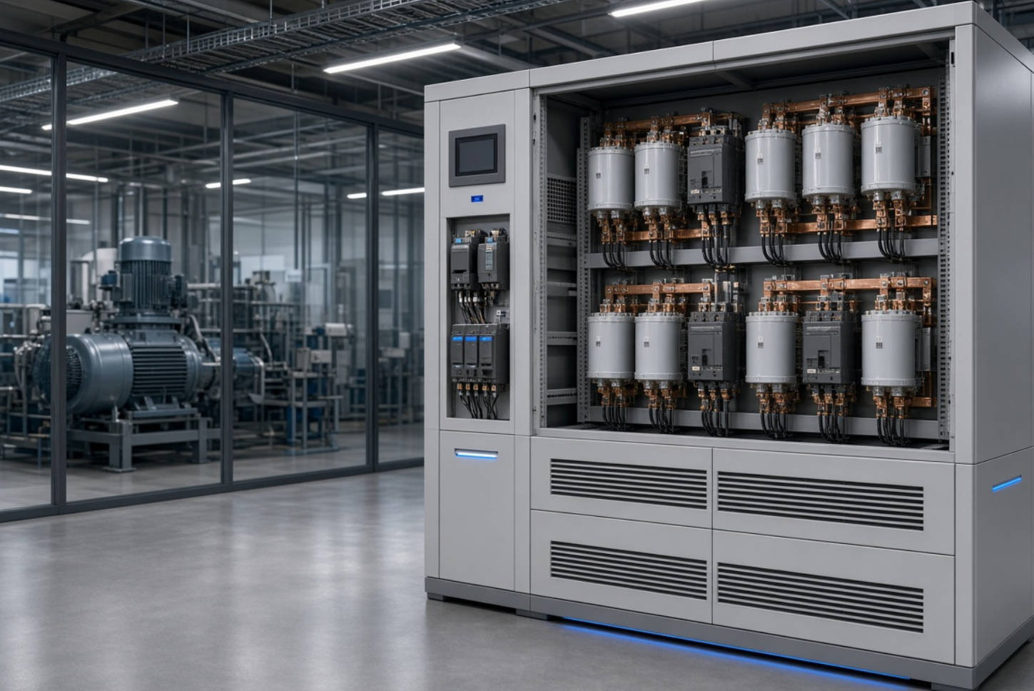
Industrial electrical loads use different components of power:
- Active power, measured in kilowatts (kW), performs useful work.
- Reactive power, measured in kilovolt-amperes reactive (kvar), supports energy exchange in inductive and capacitive equipment.
- Apparent power, measured in kilovolt-amperes (kVA), represents the combined electrical demand.
Motors and transformers typically require inductive reactive power. Supplying this demand through upstream cables and transformers increases current for a given active-power requirement.
Capacitors supply capacitive reactive power locally, offsetting part of the inductive demand. This reduces the reactive power that must travel through the upstream network.
For approximately sinusoidal conditions, power factor is closely associated with the phase angle between voltage and current.
In facilities with variable-speed drives, rectifiers, or other nonlinear loads, waveform distortion also affects power factor. Consequently, improving displacement power factor does not necessarily eliminate harmonic current or produce an equivalent improvement in total power factor.
A capacitor bank should therefore not be treated as a universal solution for every power-quality problem.
Properly designed compensation can improve the use of existing electrical infrastructure.
Reducing upstream reactive current can reduce resistive losses in the affected cables and transformers. The benefit depends on compensation location, loading, conductor resistance, and operating hours.
However, power factor correction does not directly reduce the mechanical energy required by a motor or the process energy consumed by a furnace.
Any energy-saving claim should distinguish reduced distribution losses from reduced production energy consumption.
A lower apparent-power requirement can release capacity in upstream equipment. This may help a facility accommodate additional loads without immediately expanding its distribution infrastructure.
The improvement must still be checked against thermal limits, protection settings, and other installation constraints.
Some electricity tariffs include reactive-energy charges, power-factor penalties, or apparent-power demand charges. Compensation may reduce these costs where the applicable tariff rewards improved performance.
There is no universal savings percentage. A credible financial assessment uses the facility's actual bills and operating profile.
Overcompensation occurs when installed capacitive output exceeds the inductive reactive demand at the relevant operating point.
The result is net capacitive reactive power and, under conventional terminology, a leading power factor.
The most common cause is a mismatch between equipment capacity and changing load conditions.
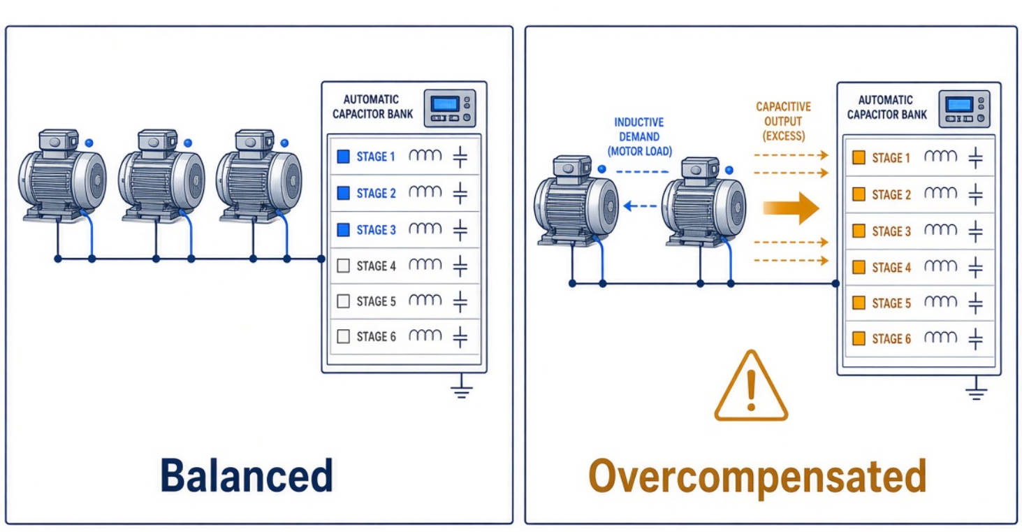
A capacitor bank selected for daytime production may be excessive during lunch breaks, overnight operation, or weekends.
When motors stop but capacitors remain connected, the reactive-power balance changes. A bank that performs correctly at full production can become unsuitable at minimum demand.
Automatic capacitor banks adjust capacity by switching individual stages.
If the smallest stage exceeds the remaining reactive demand, the controller cannot achieve a close match. It may alternate between undercompensation and overcompensation.
Step size is therefore as important as total installed kvar.
Incorrect current-transformer polarity, phase association, sensing location, or controller settings can produce inappropriate switching decisions.
A failed contactor can also leave a stage connected when the controller requests disconnection.
Before increasing capacity, verify that the existing system measures and switches correctly.
A leading power factor is an operating condition, not automatic evidence of equipment damage. Its consequences depend on network strength, compensation magnitude, equipment characteristics, and operating mode.
Excess capacitive reactive power can raise voltage, particularly in weaker networks or during light loading.
Persistent excessive voltage can increase equipment stress. However, the actual voltage change should be measured or calculated rather than assumed.
Generators can be more sensitive to leading reactive current than utility-fed networks. Excessive capacitive loading may interfere with voltage regulation and, in some circumstances, trigger instability or protective shutdown.
Generator-mode compensation settings should be checked against the generator manufacturer's capability limits.
Capacitors interact with system inductance. Under unfavorable conditions, this interaction can amplify harmonic currents or voltages.
Importantly, resonance can occur even when the fundamental-frequency compensation capacity appears correct. Preventing overcompensation does not, by itself, eliminate harmonic risk.
For a predominantly sinusoidal load, an initial compensation estimate is:
Qc=P(tanφ1−tanφ2)
Where:
- Qc is required compensation in kvar.
- P is active power in kW.
- φ1 corresponds to the initial displacement power factor.
- φ2 corresponds to the target displacement power factor.
Consider a load operating at 100 kW with an initial power factor of 0.75. The target is 0.93.
Using rounded tangent values:
Qc≈100(0.88−0.40)=48 kvar
Approximately 48 kvar is required at that operating point.
This calculation is a starting point, not a complete specification. Final selection must account for load variation, voltage, harmonics, switching arrangement, and available equipment ratings.
Suppose the facility's active load falls to 30 kW while its uncompensated power factor remains 0.75.
Its inductive reactive demand is approximately:
Q≈30×0.88=26.4 kvar
If the full 48 kvar bank remains connected, capacitive output exceeds that demand by approximately 21.6 kvar.
This illustrative example explains why sizing exclusively from peak production conditions can lead to poor light-load performance.
Equipment selection should follow the measured load profile rather than a preference for the largest or most sophisticated system.
| Compensation approach | Suitable operating conditions | Main design consideration |
|---|---|---|
| Fixed capacitor bank | Relatively steady inductive demand | Prevent excessive output at minimum load |
| Automatically switched bank | Demand changes in discrete operating patterns | Select appropriate stage sizes and controller settings |
| Thyristor-switched bank | Frequent or rapid switching requirements | Match response capability to the load |
| Static var generator | Rapidly changing reactive demand | Verify operating range and compensation capability |
| Hybrid arrangement | Large base demand with variable residual demand | Coordinate capacitor stages and dynamic equipment |
A hybrid arrangement can use capacitor stages for relatively stable demand and dynamic equipment for the remaining fluctuations.
This approach may balance equipment cost and control performance. However, controllers must operate coherently.
Poor coordination can cause unnecessary switching or opposing compensation commands. The system should be evaluated as an integrated design, not a collection of independent products.
Facilities using drives, converters, or rectifiers need a harmonic assessment before capacitor installation.
A detuned reactor is connected in series with a capacitor stage. The combination is designed with a resonance frequency below the relevant lowest significant harmonic.
This helps reduce the risk of harmful resonance and capacitor overloading.
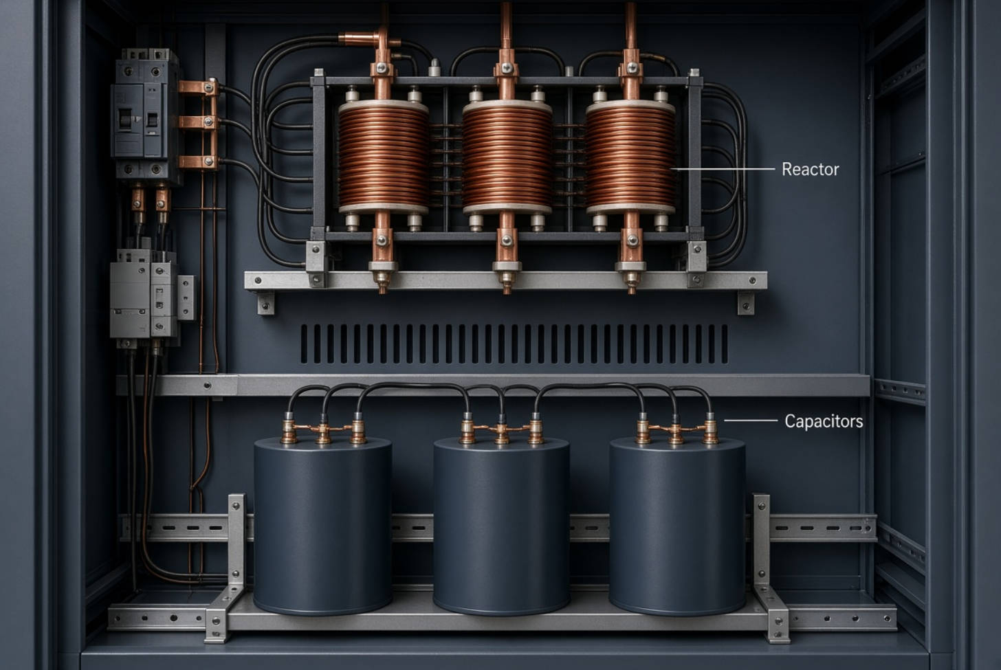
Common reactor impedance values include 5.7%, 7%, and 14%, but none is universally suitable.
Selection depends on:
- System frequency and operating voltage.
- Harmonic spectrum and distortion levels.
- Network impedance and supply configuration.
- Capacitor voltage and current ratings.
- Thermal conditions and applicable signaling frequencies.
The reactor changes the voltage across the capacitor. Capacitor selection must therefore consider the complete reactor-capacitor assembly.
A detuned bank primarily makes compensation more suitable for a harmonic environment.
It does not automatically remove every harmonic problem or guarantee compliance with a site's distortion limits.
Where harmonic reduction is required, dedicated filtering should be evaluated separately.

From a manufacturer's perspective, commissioning is where design assumptions must be tested against actual operation.
1. Record representative operating conditions. Include peak production, partial load, shutdown periods, and generator operation where applicable.
2. Measure the relevant electrical quantities. Record kW, kvar, voltage, current, power factor, and harmonic distortion.
3. Verify sensing and wiring. Confirm current-transformer polarity, ratio, phase association, and measurement location.
4. Check every compensation stage. Compare switching commands with actual contactor status and measured output.
5. Review controller settings. Check the target, stage sizes, switching delays, and reconnection requirements.
6. Test load reductions. Confirm that unnecessary stages disconnect when production demand falls.
7. Establish a maintenance baseline. Record operating temperatures, alarms, stage availability, and electrical measurements.
Work inside electrical equipment requires qualified personnel, appropriate isolation, and verified capacitor discharge procedures.
Different industries share a common challenge: their electrical demand changes with production.
Metallurgical plants may have rapidly varying process loads. Petrochemical facilities may depend on large motor systems. Textile and paper plants can combine substantial motor demand with drive-generated harmonics.
The practical lesson is to define operating modes before selecting compensation.
A useful specification identifies minimum demand, normal production, maximum production, and any alternative supply arrangements. This gives equipment designers a clearer basis for selecting capacity, stages, reactors, and controls.
DINGNUO ELECTRIC CO., Ltd. provides capacitor and reactor products, technical support, and power-quality solutions for domestic and international industrial applications.
Our application scope includes metallurgy, petrochemicals, automotive manufacturing, paper, textiles, building materials, and municipal infrastructure.
For a focused technical discussion, share your single-line diagram, supply voltage and frequency, transformer rating, load measurements, harmonic data, and existing compensation details.
Ask our team to review capacitor and reactor selection against your operating conditions. The objective is balanced compensation—not simply more installed kvar.
Reactive power compensation offsets inductive reactive demand. Overcompensation occurs when capacitive output exceeds that demand, producing a net capacitive condition. The same bank can provide appropriate compensation at high load and excessive compensation at low load.
Not necessarily. The target should reflect tariff requirements, operating variation, controller capability, and equipment limits. A setting close to unity requires careful control to avoid unwanted leading operation as demand changes.
Check reactive-power direction and the meter's leading or lagging indication during light-load periods. A high numerical power factor alone is insufficient. Confirm the meter's sign convention before interpreting positive or negative kvar readings.
Standard capacitor banks are not harmonic filters and may amplify distortion under unfavorable network conditions. Detuned reactors help manage capacitor-bank interaction with harmonics, while dedicated filters address harmonic mitigation requirements.
Its remaining connected capacity may exceed the reduced inductive demand. Other possibilities include unsuitable stage sizes, incorrect sensing, controller settings, or a failed switching device. Check operation before replacing equipment.
Provide voltage, frequency, transformer and network information, measured load profiles, harmonic measurements, environmental conditions, and control requirements. Existing equipment ratings and generator operating details also help establish a suitable design.
1. Shanghai Yingtong Electric Co., Ltd. "Reactive Power Compensation and Over Compensation." August 19, 2024. Original article used to identify the topic, existing coverage, and areas requiring expansion. [Read the original article]. [ytelect]
2. Schneider Electric. Electrical Installation Guide: "Theoretical Principles to Improve Power Factor." Technical basis for reactive-power compensation and the capacitor-sizing formula, including the 100 kW calculation example. [Read the technical guide]. [electrical-installation]
3. Schneider Electric. Electrical Installation Guide: "Possible Solutions for Power-System Harmonics." Technical basis for capacitor harmonic loading, detuned reactor arrangements, common reactor impedance values, and capacitor voltage considerations. [Read the technical guide]. [electrical-installation]
4. Schneider Electric. Power Factor Correction Catalogue. Document PFCED310003EN. Reference for compensation calculation, installation location, fixed and automatic compensation, dynamic applications, and reactor selection considerations. [Read the catalogue]. [www1.lk]
5. Schneider Electric. "Impact of Leading Power Factor on Data Center Generator Systems." Reference for the relationship between leading reactive current and generator voltage-regulation instability. Its application-specific discussion should not be interpreted as a universal limit for every generator. [Read the publication page]. [se]
6. Consulting-Specifying Engineer. "Your Questions Answered: Evolution of Power Factor Correction in Low-Voltage Distribution Networks." October 6, 2021. Expert discussion of leading-power-factor detection, dynamic compensation, and capacitor-bank tuning. [Read the expert discussion]. [csemag]
7. DINGNUO ELECTRIC CO., Ltd. Company description supplied for this article. Source for manufacturer positioning, product focus, technical-support scope, and stated application industries. No public company-information page or independently verified project records were supplied.


