
Views: 289 Author: Dingnuo Electric Publish Time: 2026-08-22 Origin: Site


Content Menu
● What Is a Dynamic Reactive Power Correction Device?
● Why Industrial Facilities Need Dynamic Reactive Power Compensation
● Dynamic Compensation vs. Conventional Capacitor Banks
● The Harmonic Risk: Why Capacitors and Reactors Must Be Matched
>> Why a standard capacitor bank may fail
● How to Select the Right Dynamic Reactive Power Correction Device
>> 1. Establish the operating baseline
>> 2. Measure harmonic conditions
>> 3. Calculate compensation capacity
>> 4. Choose switching technology
>> 5. Confirm protection and installation details
● Industry Applications and Typical Challenges
>> Example: A drive-intensive production line
● Practical Installation and Maintenance Checklist
● Why Work With DINGNUO ELECTRIC?
● Request a Power Quality Assessment
● FAQs
>> 1. What is the difference between power factor correction and harmonic filtering?
>> 2. Can I install a capacitor bank without a reactor?
>> 3. When should I use thyristor-switched capacitor banks?
>> 4. What power factor should an industrial facility target?
>> 5. Can dynamic reactive power correction reduce electricity costs?
>> 6. Why do capacitors fail repeatedly in a factory?
>> 7. What data should I provide for a compensation-system proposal?
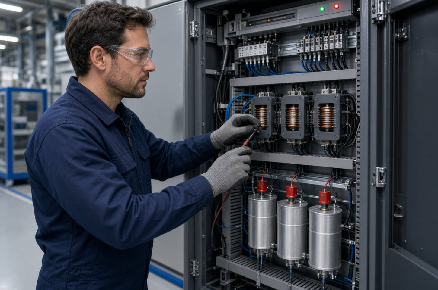
Industrial power systems are changing rapidly. Variable-frequency drives, welding machines, rectifiers, UPS systems, automation equipment, and renewable-energy interfaces can improve production efficiency—but they can also create reactive-power demand and harmonic distortion. A properly engineered dynamic reactive power correction device helps industrial facilities stabilize power factor, reduce avoidable capacity losses, and support reliable electrical operation.
At DINGNUO ELECTRIC CO., Ltd., we design capacitor and reactor-based power quality solutions for demanding industrial applications. Our approach combines application analysis, equipment selection, harmonic-risk assessment, and technical support to help customers address real operating conditions—not simply install a capacitor bank and hope for improvement.
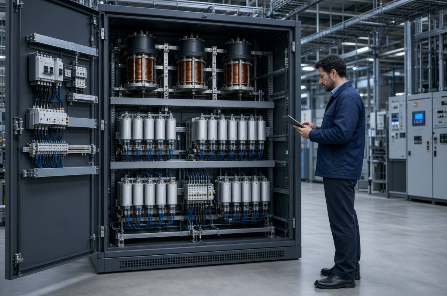
A dynamic reactive power correction device is an automated power quality system that monitors reactive-power demand and switches compensation capacity in response to load changes. Its primary purpose is to improve the power factor of an electrical system while helping maintain stable voltage and efficient use of transformer, cable, and switchgear capacity.
In practical industrial environments, inductive equipment such as motors, transformers, pumps, compressors, cranes, and welding machines consumes reactive power. Reactive power does not directly perform useful mechanical work, but it is required to establish electromagnetic fields in inductive loads. When reactive-power demand becomes excessive, the facility may experience a lower power factor, higher current, increased electrical losses, and possible utility penalties.
A dynamic compensation system generally combines:
- Power capacitors to supply capacitive reactive power
- Reactors to limit inrush current, reduce resonance risk, or form detuned filter branches
- Automatic power factor controllers to measure power factor and control switching stages
- Contactors, thyristor switches, or hybrid switching units for capacitor-step operation
- Protection components such as fuses, circuit breakers, thermal protection, and discharge resistors
- Monitoring functions for voltage, current, power factor, harmonic indicators, alarms, and operating status
The correct configuration depends on the load profile. A plant with slow and predictable load variation may use contactor-switched capacitor banks. A facility with fast-changing loads—such as welding, crane operation, rolling mills, or rapidly fluctuating drives—may require thyristor-switched or hybrid dynamic reactive power compensation.
Power factor is commonly expressed as the relationship between real power and apparent power:
Power Factor=kW/kVA
A lower power factor means the system must carry more current to deliver the same useful active power. This can consume valuable capacity in transformers, cables, generators, busbars, and switchgear.
The U.S. Department of Energy notes that low power factor is costly and inefficient, and that industrial inductive loads such as motors and transformers are common contributors. It also notes that utilities may impose charges when customer power factor falls below specified thresholds, with 0.95 often used as an example benchmark.
A well-designed dynamic reactive power correction device can help a facility:
- Improve power factor and reduce reactive-power demand from the utility
- Release electrical capacity in transformers, feeders, and distribution equipment
- Reduce I⊃2;R losses caused by unnecessarily high current
- Support voltage stability during changing load conditions
- Lower risk of power-factor penalties, where applicable
- Improve system visibility through power-quality monitoring
- Protect capacitor banks when harmonic conditions are evaluated and addressed correctly
However, reactive-power correction is not a universal cure for every power-quality issue. If the network has significant harmonic distortion, blindly adding capacitors can create or worsen resonance. This is why capacitor selection must be connected to harmonic measurement and system engineering.
The table below helps clarify which power factor correction approach may be appropriate.
| System Type | Best for | Switching Speed | Main Consideration |
|---|---|---|---|
| Fixed capacitor bank | Stable, continuous base load | No switching | May overcompensate under light load |
| Contactor-switched automatic capacitor bank | Gradually changing industrial loads | Seconds | Suitable for many conventional motor loads |
| Thyristor-switched capacitor bank | Rapid load changes | Milliseconds | Higher response speed and reduced switching transients |
| Detuned capacitor bank | Systems with moderate harmonic risk | Depends on switching technology | Requires reactor selection based on network conditions |
| Harmonic filter solution | Significant harmonic-producing loads | Application-specific | Must be designed from harmonic measurements |
| Active power quality solution | Complex, variable harmonic conditions | Fast electronic response | Often used where passive solutions alone are insufficient |
For a textile mill, paper plant, building-materials factory, or petrochemical site, the most suitable design depends on actual load behavior—not only installed motor capacity. We recommend evaluating operating schedules, transformer ratings, monthly electricity data, and measured harmonic conditions before finalizing a solution.
Modern industrial sites increasingly operate nonlinear loads. These loads draw current in pulses rather than as a smooth sinusoidal waveform. Common sources include:
- Variable-frequency drives
- Soft starters
- Rectifiers and DC power supplies
- Arc furnaces and welding equipment
- UPS systems
- LED lighting drivers
- CNC machines and automated production equipment
- Solar inverters and battery energy storage interfaces
Harmonics can contribute to overheating, capacitor overload, nuisance tripping, transformer stress, measurement errors, and shortened equipment life. IEEE 519-2022 provides harmonic-control objectives for systems containing linear and nonlinear loads, with distortion limits considered at the user's point of common coupling.
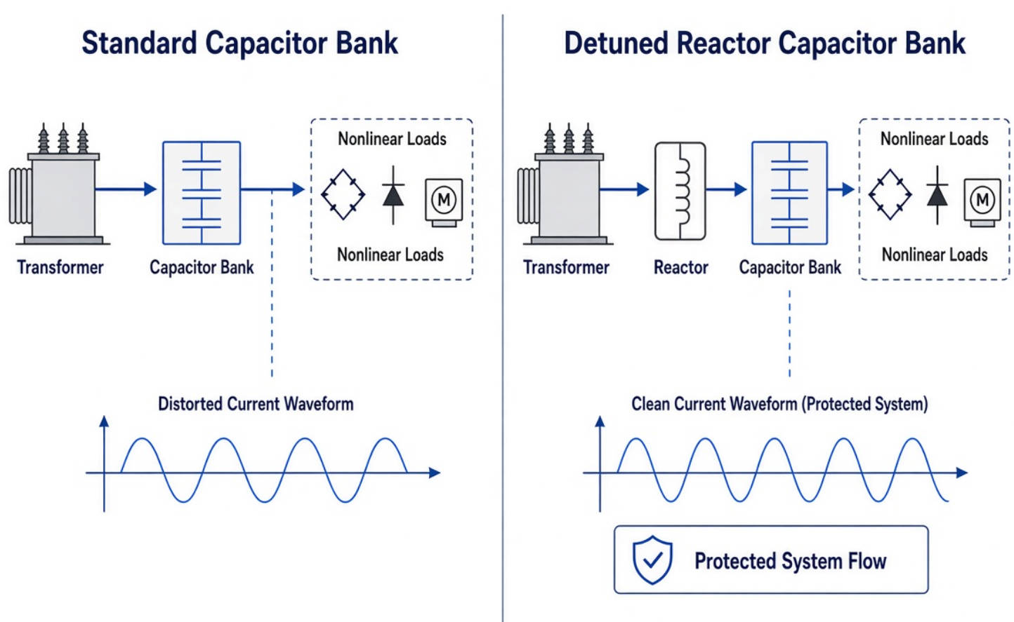
A capacitor bank changes the impedance of the electrical network. If the capacitor bank interacts with the inductance of transformers, cables, or motors at a harmonic frequency, resonance may occur. This can amplify harmonic current or voltage rather than reduce it.
Warning signs include:
- Repeated capacitor fuse failures
- Bulging capacitors or overheating cabinet components
- Frequent contactor damage
- High capacitor current despite normal reactive-power demand
- Unexplained relay trips
- Transformer or neutral overheating
- Rising total harmonic distortion after compensation is installed
A detuned reactor is often installed in series with capacitors to shift the resonance point away from dominant harmonic frequencies. This helps protect the capacitor bank and prevents the compensation system from becoming a harmonic amplifier.
IEC 60831-1 applies to self-healing shunt capacitors for AC systems rated up to 1,000 V, including equipment intended for power factor correction and filter circuits.
Selecting a solution begins with electrical data, not product catalog size. From an engineering perspective, the following workflow reduces the risk of undersizing, overcompensation, or harmonic-related equipment failure.
Collect at least one complete operating cycle of data. For many factories, this should include weekday and weekend production conditions, peak-shift operation, and low-load periods.
Key information includes:
- Transformer rated capacity and operating load
- Main incoming voltage and frequency
- Existing power factor range
- Maximum kW demand and kVA demand
- Reactive power demand in kvar
- Monthly utility billing data
- Existing capacitor-bank configuration
- Major inductive and nonlinear loads
- Expansion plans for new drives, automation, or production lines
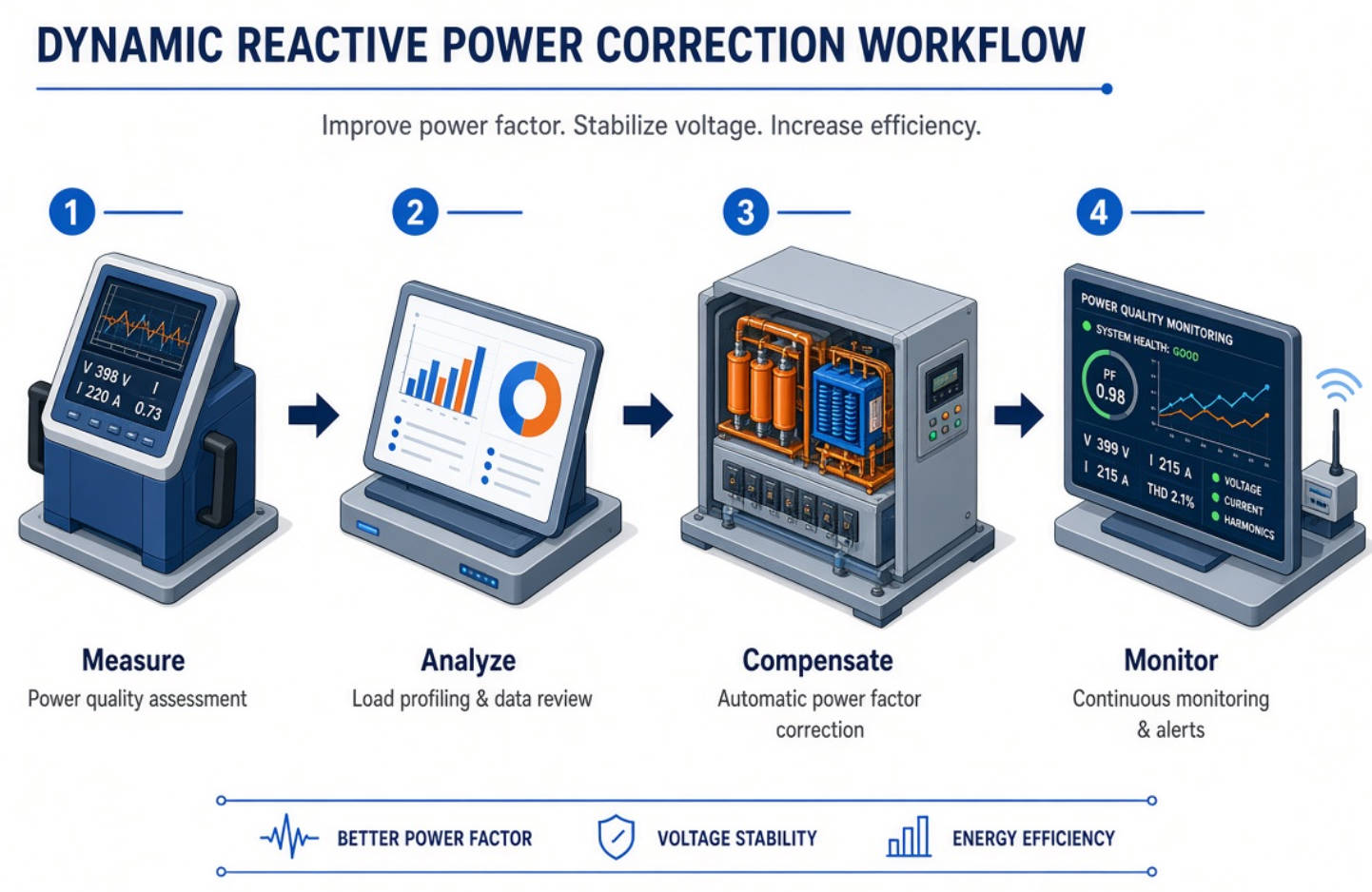
A power-quality analyzer should record voltage and current waveforms at the main incoming point and, where needed, at major load feeders. The goal is to identify the dominant harmonic orders and determine whether capacitor-bank detuning or filtering is required.
Do not rely only on a brief spot measurement. Production loads may change during different shifts, batches, or operating modes.
The reactive-power compensation requirement is commonly estimated using:
Qc=P(tanφ1−tanφ2)
Where:
- Qc is required capacitor capacity in kvar
- P is active power in kW
- φ1 is the existing power-factor angle
- φ2 is the target power-factor angle
For example, a facility operating at 800 kW may need a substantially different kvar capacity depending on whether its current power factor is 0.78, 0.85, or 0.92. The final selection must also account for load variation, step size, harmonic conditions, voltage tolerance, and future expansion.
Use the speed of load change as a decision factor:
- Choose contactor switching for conventional, slowly changing loads.
- Choose thyristor switching for rapid and frequent reactive-power fluctuations.
- Choose a hybrid solution when the application requires a balance between response speed, operating life, and investment cost.
A reliable system requires more than capacitors. Review reactor ratings, thermal conditions, cabinet ventilation, cable sizing, fuse coordination, control logic, discharge time, maintenance access, and communications requirements.
DINGNUO ELECTRIC supports industrial customers that need dependable reactive-power compensation and harmonic-control solutions across multiple sectors.
| Industry | Typical Electrical Challenge | Recommended Engineering Focus |
|---|---|---|
| Metallurgy | Arc furnaces, rolling equipment, large motors, rapidly changing load | Fast compensation, harmonic evaluation, robust thermal design |
| Petrochemical | Pumps, compressors, process drives, continuous operation | Reliability, detuned compensation, condition monitoring |
| Automotive | Welding systems, robotics, automation lines, variable-speed drives | Fast dynamic response and harmonic mitigation |
| Paper | High-power drives, pulping equipment, continuous process loads | Step optimization, harmonic assessment, transformer-capacity utilization |
| Textile | Variable-speed motors and frequent production changes | Automatic switching and modular expansion |
| Building materials | Crushers, kilns, conveyors, large motor loads | Power factor improvement, equipment protection, stable voltage support |
| Municipal projects | Pumps, water treatment, HVAC, public infrastructure | Remote monitoring, dependable protection, lifecycle service |
Consider a plant that adds multiple variable-frequency drives to improve process control. The facility may initially see better production efficiency but later encounter capacitor overheating and repeated fuse failures. The root cause may not be defective capacitors; it may be harmonic interaction between the VFDs, transformer impedance, and the existing capacitor bank.
In this situation, the right response is to measure the system, identify dominant harmonics, reassess capacitor-step capacity, and determine whether a detuned reactor bank, passive filter, active harmonic filter, or combined solution is appropriate. This is the difference between product replacement and power-quality engineering.
A dynamic reactive power correction device performs best when it is specified, installed, and maintained as part of the broader electrical system.
- Verify transformer capacity, system voltage, and short-circuit conditions
- Measure power factor and harmonic distortion under representative loads
- Identify large motor starts, VFDs, welders, UPS systems, and other nonlinear loads
- Define the target power factor with reference to local utility rules and site operating goals
- Allow capacity for planned production expansion
- Confirm whether detuned reactors or harmonic filters are required
- Verify phase sequence, current-transformer orientation, and controller settings
- Confirm each capacitor step switches correctly
- Check capacitor current, reactor temperature, and cabinet ventilation
- Test alarm, protection, and communication functions
- Compare actual post-installation power factor with the design target
- Recheck harmonic levels after the system is energized
- Inspect capacitors for swelling, leakage, or discoloration
- Tighten electrical connections according to maintenance procedures
- Check contactors, thyristor modules, fuses, fans, and thermal conditions
- Review controller event logs and switching frequency
- Conduct periodic power-quality measurements after major load changes
Power quality is application-specific. An effective dynamic reactive power correction device must reflect the customer's electrical network, load characteristics, operating rhythm, harmonic environment, and future expansion plans.
DINGNUO ELECTRIC CO., Ltd. provides capacitor, reactor, reactive-power compensation, and harmonic-control solutions for industrial and municipal power systems. Our service perspective focuses on practical engineering support: understanding the system first, then recommending a solution that balances power-factor performance, harmonic safety, reliability, and lifecycle value.
Whether you operate a metallurgy facility, petrochemical plant, automotive production line, paper mill, textile factory, building-materials site, or municipal project, our team can help evaluate your power-quality challenges and develop a suitable technical path.
If your facility experiences low power factor, utility penalties, capacitor failures, overheating, unexplained trips, or increasing harmonic distortion, do not treat these symptoms as isolated component issues.
Contact DINGNUO ELECTRIC today to discuss your load profile, transformer capacity, existing compensation equipment, and harmonic measurement needs. We can help you identify the right dynamic reactive power correction and harmonic-control strategy for safer, more efficient, and more reliable operation.
Power factor correction reduces reactive-power demand, usually through capacitors. Harmonic filtering reduces unwanted waveform distortion caused by nonlinear loads. In many industrial facilities, both functions must be considered together because capacitors can be affected by harmonics.
Possibly, but only after evaluating harmonic conditions. In systems with meaningful nonlinear loads, a conventional capacitor bank may face resonance, overload, or premature failure. A detuned reactor is often recommended where harmonic risk exists.
Use thyristor-switched systems when reactive-power demand changes rapidly, such as in welding operations, crane systems, rolling mills, highly dynamic motor loads, or automated production lines with frequent load variation.
The appropriate target depends on utility requirements, tariff structure, operating conditions, and local regulations. Many facilities aim to maintain power factor near or above 0.95, but the target should be confirmed through site-specific analysis rather than applied blindly.
It can reduce costs where low power factor creates utility charges or where reducing current-related losses and releasing system capacity provides measurable value. Actual savings depend on tariff rules, load profile, existing power factor, and compensation design.
Common causes include excessive harmonic current, resonance, overvoltage, poor ventilation, incorrect capacitor rating, unsuitable switching equipment, loose connections, and insufficient maintenance. A power-quality measurement is usually the best first step.
Provide transformer details, single-line diagrams if available, electricity bills, existing power factor, major load list, VFD or rectifier capacity, operating schedule, current compensation equipment, and recent harmonic measurements. If no measurements exist, arrange a site survey or power-quality study.
1. IEEE Standards Association. "IEEE 519-2022: IEEE Standard for Harmonic Control in Electric Power Systems." Available at: [https://standards.ieee.org/ieee/519/10677/] [standards.ieee]
2. IEEE Standards Association. "IEEE SA – P519: Harmonic Control in Electric Power Systems." Available at: [https://standards.ieee.org/ieee/519/11811/] [standards.ieee]
3. U.S. Department of Energy. "Reducing Power Factor Cost." Available at: [https://www.energy.gov/sites/prod/files/2014/04/f15/mc60405.pdf] [energy]
4. International Electrotechnical Commission. "IEC 60831-1: Shunt Power Capacitors of the Self-Healing Type for AC Systems up to and Including 1,000 V." Available at: [https://standards.globalspec.com/std/1683977/iec-60831-1] [standards.globalspec]
5. IEC Technical Committee 33. "IEC 60831-1:2014—Performance, Testing, Rating, Safety Requirements and Guide for Installation and Operation." Available at: [https://cdn.standards.iteh.ai/samples/19102/9bb83631a3bc4893bbf340265e9c6c8f/IEC-60831-1-2014.pdf] [cdn.standards.iteh]
6. YT Electric. "Dynamic Reactive Power Correction Device." Available at: [https://www.ytelect.com/blog/dynamic-reactive-power-correction-device_bk_19] [ytelect]


