


| Quantity: | |
|---|---|


Functional feature
The DNKL-200 Intelligent Controller is a new type of power distribution measurement and control device that integrates data acquisition, reactive power compensation, and power grid parameter analysis. It is suitable for monitoring and reactive power compensation control in 0.4kV, 50Hz AC low-voltage power distribution systems. With a high-speed digital signal processor and utilizing AC sampling, the device features a 128×64 dot-matrix LCD display as its human-machine interface. It supports power distribution monitoring, reactive power compensation, harmonic analysis, and an adaptive frequency algorithm, with input signals ranging from 45Hz to 55Hz. RJ45 communication interface facilitates connectivity with smart capacitors.
Main Features
1. Display
Adopting a Chinese LCD display screen, it can monitor the relevant parameters of the power grid in real time, display the set parameters and work status. Real time display of grid voltage, current, power factor, active power, reactive power, apparent power, total harmonic distortion rate of voltage, total harmonic distortion rate of current, frequency, voltage waveform, current waveform, capacitor switching status, and fault alarm status.
2. Reactive power compensation
The sampled physical quantity is reactive power, no switching oscillation, and no compensation dead zone.It has two operation modes manual switching and automatic switching. It has an intelligent switching mode, and the capacitance of each group can be freely set. The capacitance compensation methods are -type compensation and t-shaped compensation. The control output mode is RJ45 network port output, and up to 64 output channels can be controlled.
3. Data statistic and communication(optional)
Capable of capacitor switching statistics function. The communication interface is a 485 standard interface, and the communication protocol complies with the MODBUS industrial protocol. It can upload statistical data and real-time data of the power grid, and can be controlled by a remote computer to switch capacitors on and off.
4. Set up
Current conversion ratio, voltage conversion ratio, overvoltage/undervoltage protection, harmonic voltage/current protection,switching threshold coefficient, switching waiting delay, switch response waiting time, cycle switching interval time,capacitor discharge time, protection duration, manual duration,capacitor capacity and other parameters can be set. Equipped with automatic memory for setting parameters, it will not be lost in case of power failure.
5. Protect
Equipped with self check reset and watchdog function
Equipped with overvoltage and undervoltage protection functions
Equipped with harmonic voltage and current protection functions
Equipped with low current protection function
Equipped with low power factor protection function
When any protection is activated, the protection amount will be displayed in reverse
Installation and Commissioning
◆ Safety Precautions
Ø Both the power supply input and the CT secondary side pose a risk to personal safety. Therefore, operators must strictly adhere to relevant safety operating procedures during installation, commissioning, and maintenance to ensure the safety of both personnel and equipment.
When wiring, select the appropriate wire gauge and strictly follow the wiring diagram to ensure the safety and reliability of operation.
◆ Installation and Wiring
First, insert the controller into the device panel opening(138mmX138mm)from the front, then push the installation card into the left and right card slots of the controller, and tighten the screws to fix the controller to the device panel.
Parameter
◆ Conduction of use
Altitude: ≤2500 meters
Environment Temperature: -20°C to +65°C
Relative Humidity: 20% to 90% (at 40°C)
Atmospheric Pressure: 79.5–106.0 kPa
◆ Power supply conditions
Operating Voltage: AC 220 V or AC 380 V
Permissible Deviation: ±20%
Sampling Current: 0–5 A
Operating Frequency: 50 Hz ±5%
◆Control Parameters
Measured physical quantity: Reactive power
Control sensitivity: 30mA
◆Measurement Accuracy:
Voltage: ±0.5% Current: ±0.5%
Active Power: ±1% Reactive Power: ±1%
Frequency: ±0.5% Power Factor: ±1%
◆Mechanical Parameters:
Dimensions: 144 × 144 mm
Cutout Dimensions: 138 × 138 mm
Thickness: 100 mm
◆Compliance Standards
JB/T9663-2013
DL/T597-1996
Installation and Commissioning
◆ Safety Precautions
Ø Both the power supply input and the CT secondary side pose a risk to personal safety so operators must strictly adhere to relevant safety operating procedures during installation, commissioning, and maintenance to ensure the safety of both personnel and equipment.
Ø When wiring, select the appropriate wire gauge and strictly follow the wiring diagram to ensure the safety and reliability of operation.
◆ Installation and Wiring
First, insert the controller into the cutout (138mm × 138mm) on the device panel from the front, then push the installation card into the slot on the left stone side of the controller, and tighten the screws to secure the controller to the device panel.
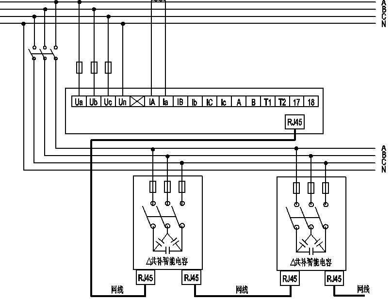
Control method:RJ45 Control Object: Smart Capacitor
Terminal definition explanation:
Terminal number | Status | Detailed Explanation |
Ua、Ub、Uc、Un | Voltage Input | Connect to three-phase voltage and neutral line |
IA、Ia | Current Input | Connect to (IA, Ia) single-phase current transformers |
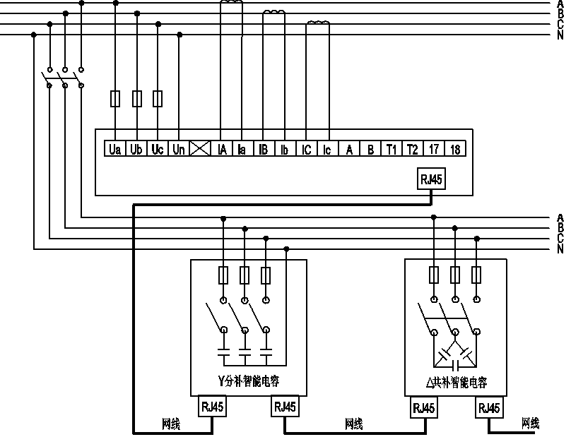
Control method:RJ45 Control Object: Smart Capacitor
Terminal definition explanation:
Terminal number | Status | Detailed Explanation |
Ua、Ub、Uc、Un | Voltage Input | Connect the three-phase voltage and neutral wire |
IA、Ia;IB、Ib;IC、Ic | Current Input | Connect the three-phase current transformers |
Hot Tags: Intelligent Controller, China, private label, Customized, Bulk, discount, manufacturing company, suppliers, quotation


