
Views: 263 Author: Dingnuo Electric Publish Time: 2026-09-04 Origin: Site


Content Menu
● What Is an Active Harmonic Filter?
>> Active Harmonic Filter and Active Power Filter: Is There a Difference?
● Why Harmonics Matter in Industrial Power Systems
>> Typical Symptoms of Harmonic Distortion
● Active Harmonic Filter vs Passive Harmonic Filter
● AHF/APF Applications by Industry
>> Metallurgy and Heavy Industry
>> Petrochemical and Process Plants
>> Paper, Textile, and Building-Materials Production
>> Municipal and Infrastructure Projects
● How to Size an Active Harmonic Filter Correctly
>> Step 1: Conduct a Power-Quality Survey
>> Step 2: Define the Compensation Objective
>> Step 3: Select Compensation Capacity
>> Step 4: Choose the Installation Point
>> Step 5: Verify Results After Commissioning
● Standards: IEEE 519 and IEC 61000
● Expert Checklist Before Buying an AHF/APF
● Why Work With DINGNUO ELECTRIC CO., Ltd.?
● FAQ
>> 1. Is an active harmonic filter the same as an active power filter?
>> 2. Can an AHF/APF improve power factor?
>> 3. Can an active harmonic filter replace a capacitor bank?
>> 4. Where should an active power filter be installed?
>> 5. What causes high harmonic current in a factory?
>> 6. Does an AHF/APF guarantee IEEE 519 compliance?
>> 7. How do I know what size active harmonic filter I need?
Modern industrial facilities rely on variable-frequency drives, rectifiers, welding machines, UPS systems, automated production lines, EV chargers, and other non-linear loads. While these technologies improve productivity, they can also introduce harmonic currents, reduce true power factor, overload transformers, and create costly power-quality problems. An Active Harmonic Filter (AHF)—also commonly called an Active Power Filter (APF)—provides a dynamic solution by measuring distortion in real time and injecting compensating current to cancel unwanted harmonics.
For plants in metallurgy, petrochemical processing, automotive manufacturing, paper production, textiles, building materials, and municipal infrastructure, the right AHF/APF design can help improve electrical reliability, support harmonic-compliance objectives, and protect critical electrical assets.

An Active Harmonic Filter is a power-electronic device that monitors current and, in some configurations, voltage quality in an electrical distribution system. It identifies unwanted harmonic components created by non-linear loads and generates an equal-but-opposite compensating current.
The compensating current is injected back into the power network. This reduces the harmonic current seen by upstream transformers, cables, switchgear, generators, and utility connection points.
In practical terms, an AHF/APF works like an intelligent electrical "noise-cancellation" system.
Unlike conventional passive harmonic filters, which are designed around fixed inductors and capacitors, an active harmonic filter continuously adapts to changes in load conditions. That makes it especially valuable in facilities where production equipment starts, stops, accelerates, decelerates, or changes operating modes throughout the day.
In most industrial power-quality discussions, AHF and APF refer to the same category of equipment.
- AHF emphasizes harmonic-current mitigation.
- APF may describe a broader function that includes harmonic filtering, reactive-power compensation, power-factor improvement, and load-balancing support.
- The exact functions depend on the product configuration, current-transformer installation, control settings, and system requirements.
For procurement and engineering purposes, the most important question is not the label. It is whether the equipment can provide the compensation functions your site actually needs.
| Function | Active Harmonic Filter / Active Power Filter Capability |
|---|---|
| Harmonic-current mitigation | Reduces selected or broad-spectrum harmonic currents |
| Reactive-power compensation | Can compensate inductive or capacitive reactive current, depending on configuration |
| Power-factor improvement | Can improve displacement power factor and support higher true power factor |
| Three-phase load balancing | Can reduce current imbalance between phases in applicable systems |
| Neutral-current reduction | Can help reduce triplen-harmonic-related neutral current in four-wire systems |
| Dynamic response | Adjusts compensation as operating loads change |
Key takeaway: An AHF/APF should be specified by its required compensation current, harmonic spectrum, connection voltage, installation point, load behavior, and control objective—not by name alone.
Harmonics are currents or voltages at frequencies that are multiples of the fundamental supply frequency. In a 50 Hz system, common harmonic orders include the 5th, 7th, 11th, and 13th. In a 60 Hz system, the same orders occur at different absolute frequencies but create similar operational concerns.
Non-linear loads draw current in pulses rather than as a smooth sinusoidal waveform. This distorted current can circulate through the electrical network and create distortion-related losses, heating, interference, and reliability risks.
Common harmonic-producing equipment includes:
- Variable-frequency drives and soft starters
- DC motor drives and rectifier systems
- UPS systems and data-center power equipment
- Arc furnaces and welding equipment
- LED lighting drivers
- Switching power supplies
- Battery energy-storage systems
- EV fast-charging equipment
- Automated production lines and robotic systems
A plant may need an active harmonic filter if it experiences recurring electrical symptoms that cannot be explained by normal loading alone.
Watch for:
- Transformer overheating despite operating below apparent rated capacity
- Frequent capacitor-bank failures or blown fuses
- Nuisance tripping of circuit breakers or protective relays
- Overheated cables, busbars, and neutral conductors
- Voltage instability near sensitive production equipment
- Excessive noise or vibration in motors and transformers
- Poor true power factor even after capacitor-bank installation
- Utility penalties, failed power-quality assessments, or connection concerns
- Communication errors, PLC disruptions, or unexpected control-system behavior
These symptoms do not automatically prove that harmonics are the only cause. However, they justify a professional power-quality assessment using properly installed meters and a meaningful measurement period.
An active harmonic filter uses high-speed measurement, digital control, and power-electronic switching devices to calculate and inject compensating current.
The process generally follows four steps:
1. Measure the electrical system.
Current transformers measure the load current, while the controller analyzes waveform distortion, reactive current, phase imbalance, and other selected parameters.
2. Identify unwanted current components.
The controller separates the fundamental current from harmonic, reactive, and unbalanced current components.
3. Calculate compensation demand.
The system determines the magnitude and phase angle of the compensating current needed to reduce the selected disturbance.
4. Inject compensating current.
The AHF/APF produces a corrective current that opposes the unwanted current component, reducing the distortion flowing upstream.
This approach differs from a passive filter, which uses tuned capacitors and reactors to provide a low-impedance path for selected harmonic frequencies. Passive systems can be highly effective when correctly engineered, but their performance can be influenced by network impedance, capacitor aging, frequency variation, load changes, and resonance conditions.
Active filters are often selected when harmonic conditions are dynamic, multiple harmonic orders are present, expansion is likely, or reactive-power compensation and harmonic mitigation are required together.
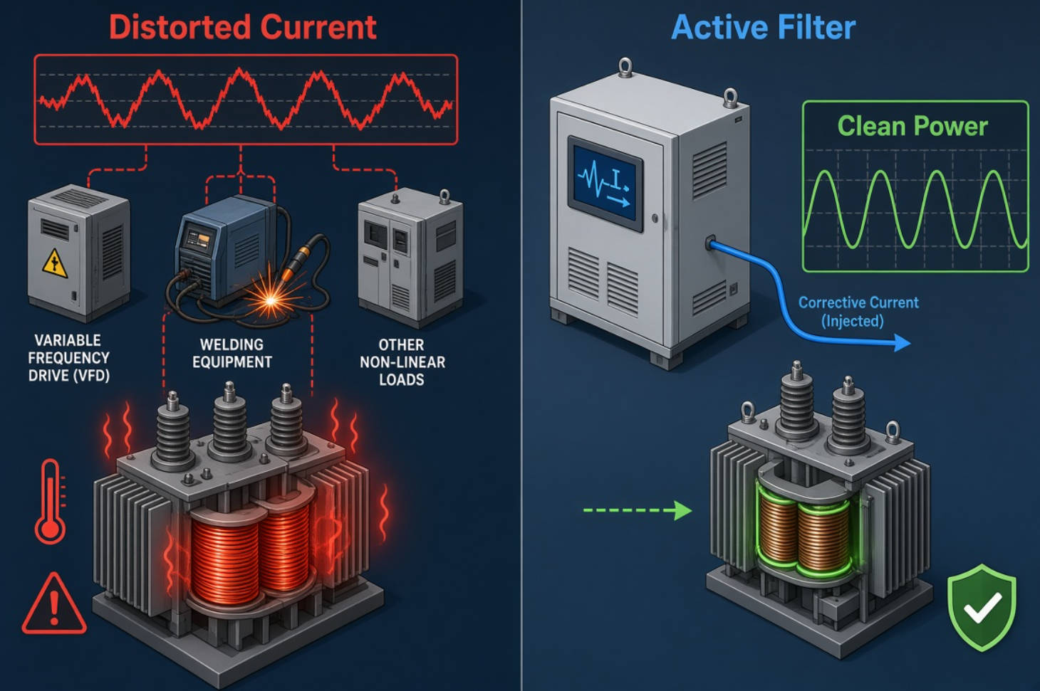
The choice between active and passive harmonic mitigation should be based on measured system conditions, not simply on initial equipment cost.
| Selection Factor | Active Harmonic Filter / APF | Passive Harmonic Filter |
|---|---|---|
| Compensation method | Injects calculated compensating current | Uses tuned capacitors and reactors |
| Harmonic range | Can address multiple configured harmonic orders | Usually targets specific harmonic frequencies |
| Response to load changes | Dynamic and adaptive | More fixed after design and tuning |
| Reactive-power compensation | Often available as an integrated function | Commonly inherent in capacitor-based designs |
| Risk of resonance | Lower when correctly applied, but system study is still required | Requires careful engineering to avoid resonance |
| Physical footprint | Often compact for its capability | Can require substantial space at high kVAR ratings |
| Initial investment | Typically higher | Often lower for stable, predictable loads |
| Best fit | Variable loads, multiple harmonics, sensitive systems | Stable harmonic spectra and well-characterized networks |
A hybrid solution can also be appropriate. For example, a detuned capacitor bank or passive filter may provide economical base reactive-power support, while an active power filter manages residual harmonics, changing loads, and dynamic compensation requirements.
Arc furnaces, rolling mills, high-power drives, welding systems, and large rectifier loads can create complex, rapidly changing harmonic conditions. In these environments, an active harmonic filter can help reduce upstream harmonic loading and stabilize power quality for sensitive auxiliary systems.
For heavy-industry projects, engineering teams should assess load cycles, transformer impedance, short-circuit capacity, existing capacitor banks, and the harmonic spectrum at different operating states.
Petrochemical facilities often depend on continuous-process equipment, motor-control centers, pumps, compressors, variable-speed drives, and automation systems. A power-quality event can affect both uptime and process stability.
An APF can be applied at the main distribution level, an MCC bus, or near a concentrated group of non-linear loads. The optimal location depends on where distortion originates and which electrical assets require protection.
Automotive plants use robotic welding, servo drives, paint-shop equipment, conveyors, presses, battery-module lines, and automation controls. Production loads can shift quickly as stations cycle on and off.
A dynamic active power filter is often beneficial where harmonic current, reactive current, and phase imbalance fluctuate together. It can support steadier electrical conditions without requiring constant manual retuning.
Paper machines, textile equipment, kiln systems, crushers, extruders, and conveyor drives frequently use VFD-based speed control. As drive penetration rises, so does the importance of evaluating harmonic performance before installing conventional capacitor compensation.
In these applications, the correct solution may include an AHF/APF, a detuned reactor capacitor bank, a passive harmonic filter, or a coordinated combination of technologies.
Water-treatment plants, rail systems, hospitals, pumping stations, airport facilities, data rooms, and public-building infrastructure increasingly depend on electronically controlled loads. Reliability requirements are high, while shutdown windows are often limited.
A modular active harmonic filter can be attractive in retrofit projects because capacity can be expanded as demand changes—provided the installation has adequate switchgear capacity, ventilation, cable sizing, and protection coordination.

AHF/APF sizing should never rely only on a facility's total transformer rating. The correct rating depends on the actual current to be compensated.
A good sizing process begins with measurement rather than assumptions.
Use a suitable power-quality analyzer at the relevant point of common coupling, main distribution board, transformer secondary, or load bus.
Measure:
- Total harmonic distortion of current and voltage
- Individual harmonic orders
- Fundamental current and peak current demand
- Reactive-power demand in kVAR
- True power factor and displacement power factor
- Three-phase current imbalance
- Neutral current, where applicable
- Voltage variation and load operating cycles
- Existing capacitor-bank switching behavior
Measurements should cover normal production, peak operation, low-load operation, shift changes, start-up events, and major process transitions.
Do not specify "harmonic filter" as a generic requirement. Define the target.
For example:
- Reduce harmonic current at the PCC
- Support an IEEE 519-based compliance objective
- Lower transformer RMS current and thermal stress
- Improve true power factor
- Reduce neutral current
- Stabilize voltage for sensitive equipment
- Prevent capacitor-bank overheating or resonance-related failures
- Support expansion of VFD, UPS, welding, or charging loads
The active filter's rated compensation current must reflect the actual harmonic and reactive current demand, including a reasonable allowance for future load growth.
An undersized unit may reduce distortion but fail to achieve the desired result during peak operating conditions. An oversized unit may increase project cost unnecessarily. A modular design can provide a balanced approach when production expansion is expected.
Common installation approaches include:
- Centralized installation: At the main low-voltage bus or transformer secondary for broad system-level compensation.
- Group installation: At an MCC, production line, or distribution section serving multiple non-linear loads.
- Local installation: Near a large harmonic-producing load, such as a high-power drive, UPS, rectifier, or welding system.
Centralized compensation is easier to manage, while local installation can prevent harmonic current from circulating through upstream cables and switchgear. The best option depends on measurements and the physical distribution architecture.
Commissioning should include before-and-after measurements under representative operating conditions. Verify not only THD values but also current loading, power factor, capacitor-bank behavior, thermal performance, and whether filter capacity is sufficient during peak demand.

Power-quality projects should be evaluated against the correct standard, contractual requirement, grid code, and local utility rule.
IEEE 519 is widely used as a framework for evaluating harmonic voltage and current distortion at the point of common coupling. It considers system characteristics such as voltage level and the ratio of available short-circuit current to maximum demand current. It is not appropriate to apply a single universal harmonic limit without understanding the measurement location and network conditions.
IEC 61000 is a family of electromagnetic-compatibility standards covering different equipment categories, test methods, emission limits, and immunity requirements. Some IEC harmonic-current emission standards apply to equipment within defined current ranges, while industrial system studies may require a broader site-specific engineering assessment.
For this reason, "IEEE 519 compliant" should be treated as an engineering objective that must be validated through measurement, network analysis, correct installation, and post-commissioning testing—not as a standalone product claim.
Before selecting an active harmonic filter supplier, ask the following questions:
1. What are the dominant harmonic orders at peak and normal load?
2. Where is the required measurement point: PCC, transformer secondary, MCC, or local load bus?
3. What harmonic-current and voltage-distortion target applies to the project?
4. Is the main problem harmonic distortion, low power factor, phase imbalance, neutral current, or a combination?
5. Are capacitor banks already installed, and are detuning reactors present?
6. What are the transformer capacity, short-circuit level, cable lengths, and system impedance?
7. Does the load change frequently, or is the harmonic spectrum relatively stable?
8. Is there enough panel space, ventilation, and electrical protection capacity?
9. Is modular expansion needed for future production growth?
10. Will the supplier provide commissioning support, settings guidance, and post-installation verification?
A supplier that starts with measurements and system analysis is more likely to deliver a durable solution than one that recommends equipment based only on the total kVA of the facility.
DINGNUO ELECTRIC CO., Ltd. is a professional manufacturer of capacitors and reactors focused on power-quality solutions for industrial and infrastructure applications. We provide advanced technology, product support, and integrated solutions for reactive-power compensation and harmonic control.
Our solutions are designed for demanding applications in:
- Metallurgy and heavy industrial production
- Petrochemical and process industries
- Automotive manufacturing
- Paper and pulp operations
- Textile production
- Building-materials manufacturing
- Municipal and national infrastructure projects
For customers facing harmonic distortion, poor power factor, capacitor-bank instability, or changing electrical loads, the right solution begins with a clear understanding of the system—not a one-size-fits-all product selection.
Contact DINGNUO ELECTRIC CO., Ltd. to discuss your power-quality measurements, operating conditions, and compensation target. Our technical team can help evaluate whether an active harmonic filter, active power filter, detuned capacitor bank, reactor solution, or coordinated system design best fits your project.
In most industrial applications, yes. The terms AHF and APF are often used interchangeably. However, some suppliers use APF to describe a broader product that combines harmonic filtering with reactive-power compensation, power-factor improvement, and phase-load balancing.
Yes. Many active power filters can compensate reactive current and improve power factor while also reducing harmonics. The final result depends on the filter's rating, control settings, available compensation capacity, and the facility's load profile.
Not always. An AHF/APF can provide dynamic reactive-power compensation, but a capacitor bank may still be a cost-effective choice for stable base-load reactive-power demand. In many facilities, a hybrid arrangement using detuned capacitors plus an active filter provides the best balance of cost and performance.
It can be installed centrally at the main distribution board, at a group-level bus such as an MCC, or locally near a major non-linear load. The right location should be determined through a power-quality survey and electrical system review.
High harmonic current is usually caused by non-linear loads such as VFDs, rectifiers, UPS systems, welding machines, switch-mode power supplies, LED drivers, battery chargers, and electronically controlled production equipment.
No equipment can guarantee compliance without considering the actual site conditions. IEEE 519-related performance depends on the measurement point, grid strength, background distortion, load current, filter capacity, system configuration, and commissioning results.
Start with a power-quality survey. Measure harmonic current, harmonic spectrum, reactive power, peak current, voltage distortion, and load variation. Size the filter according to the required compensation current and expected future growth, not only according to transformer capacity.
2. [International Electrotechnical Commission — IEC 61000 Electromagnetic Compatibility Standards]
3. [Hammond Power Solutions — Active Harmonic Filter Overview]
4. [Monolithic Power Systems — Active Filters for Harmonic Elimination]
5. [Eaton — Power Factor Correction: A Guide for the Plant Engineer]
6. [YT Electric — What Is an Active Harmonic Filter? A Complete Guide to Power Quality Solutions]
7. [YT Electric — IEC vs IEEE Standards for Active Harmonic Filters]


